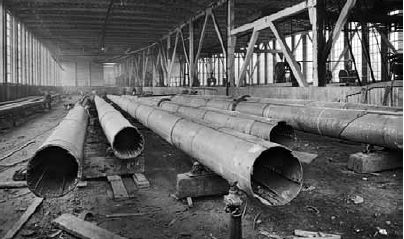
The rigging for the masts and funnels was of critical importance as all of it is highly visible. On the real Titanic, all the standing rigging - the stays and shrouds that were permanently attached to the funnels and masts for support - was galvanized steel wire rope of varying diameters. This had to be replicated in the correct scale size. Attaching the rigging without unsightly knots, and tensioning it properly, would be important. A replacement would also have to be found for the styrene kit masts since they were not rigid enough to take the tension that would be on the lines.
For the rigging, pre-waxed nylon flytying thread was used: 8/0 diameter for the majority of the lines, and 6/0 for the funnel and mast shrouds. Nitinol wire was originally considered due to its more exact scale diameter and perfect straightness, but its black color and inability to tie a knot in it led to flytying thread being the material of choice. Flytying thread was available in a light grey color, which was ideal to replicate the galvanized steel wire rope used on the real ship. To eliminate waviness in the thread from being coiled around the spool, lengths of thread first had one end clamped in a vice, pressing the upper end firmly between two fingers and sliding them out to the free end while passing a hot hair dryer along their length. It's a technique that has to be practiced, but doing it several times and doing it right resulted in straight lines free of kinks, curls and twists.
Background elevation drawings and plan details above and below right from the Hahn Titanic Plans. Used by permission of Robert Hahn.
I was fortunate enough to obtain the last set of 1:350 brass Titanic masts made by modeler Christian Schonborg in Portugal. Brass is an ideal material for masts because of its strength and rigidity. However, paint doesn't adhere to brass very well and for that reason the masts were first painted with grey primer. "Primer" is the name for the color only and has no special properties, but it would give a neutral base for the final coat of paint that was matched to the color Harland & Wolff called 'Dark Mast'.
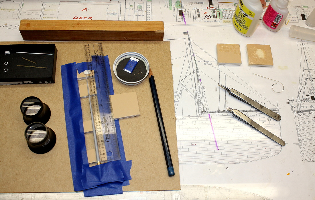
To work on the mast without scratching the paint, a jig was made by securing blocks of foamcore to a piece of cardboard, spaced at points that would not interfere with the various fittings. The mast was placed atop the blocks to elevate it off the work surface, and a piece of painter's tape at each end secured it for the work that needed to be done.
To work on the mast without scratching the paint, a jig was made by securing blocks of foamcore to a piece of cardboard, spaced at points that would not interfere with the various fittings. The mast was placed atop the blocks to elevate it off the work surface, and a piece of painter's tape at each end secured it for the work that needed to be done.

The two small brackets would accommodate the fitting for the cargo boom. The larger bracket below is for the ship's bell.
|
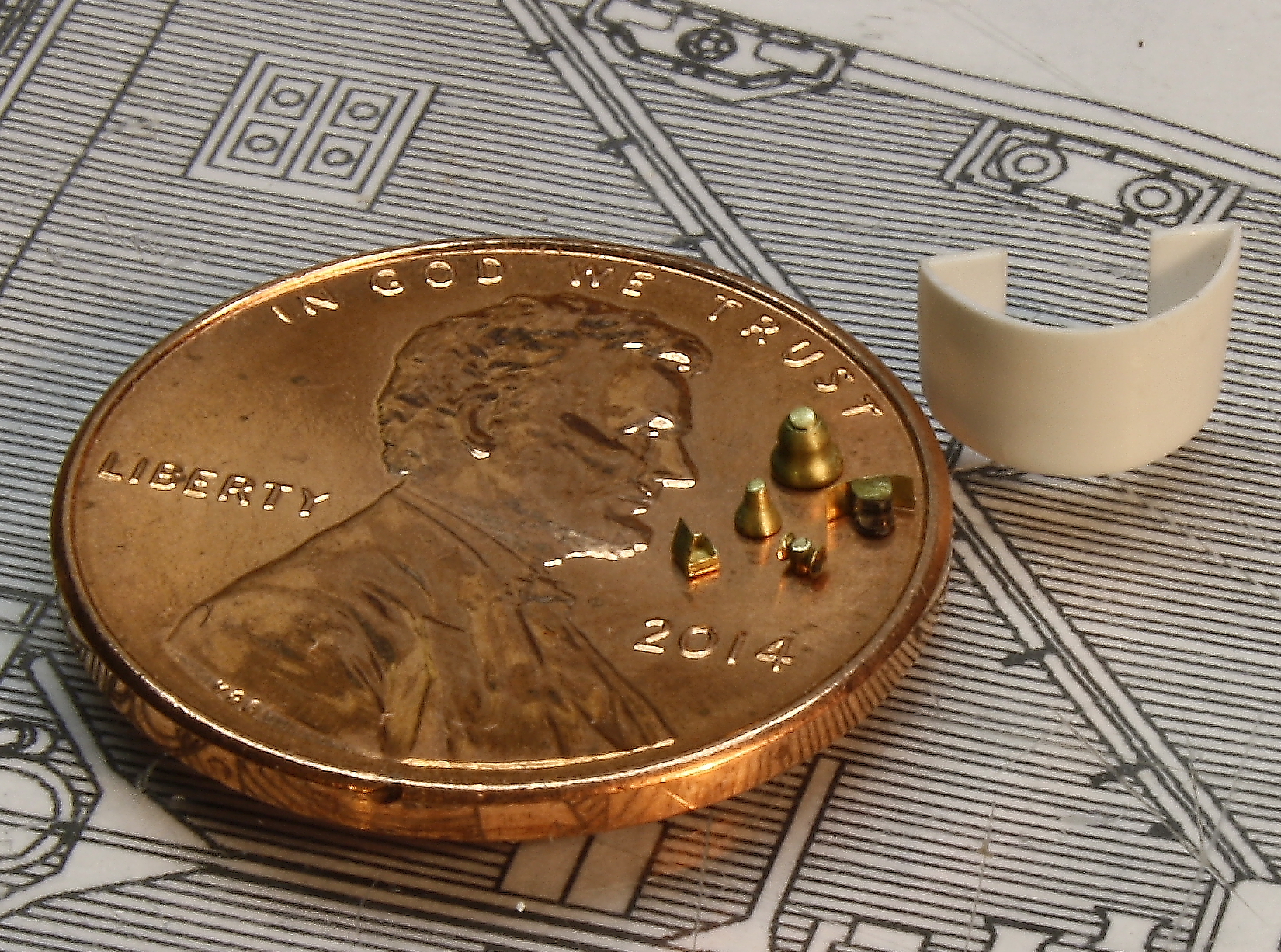
Above, the crow's nest before installation with various fittings for the crow's nest, foremast and mainmast shown next to it
|
After the masts were primed they were placed back in the jig and brackets for the bells and lamps were installed. Shown above left are the brackets for the bell and the cargo boom on the foremast. With the brackets cemented in place the masts, cargo booms and ladders were then airbrushed with the mast color (the ladders were not installed yet), and the masts returned to the jig once again. This time the supporting blocks were cushioned with soft cloth since paint scrapes off brass very easily. With the mast thus protected, the ladders, crow's nest and all the fittings were installed. (All including the crow's nest were scratchbuilt.)
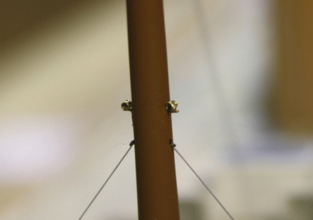
The fittings on the masts involved the smallest brasswork on the model. Shown below left at extreme magnification are the "docking lamps" on the mainmast, at left - now known with reasonable certainty to have nothing to do with docking - and at right, the masthead lamp on the foremast. The lens for this lamp was made from a section of .25mm fiber optic strand, scored several times around its circumference to replicate the pattern of the fresnel lens, and the housing was made of .001" sheet brass.
The left image below also shows the detail of the shrouds where they meet the mast. The shrouds were drilled through the mast, and very small eyes were painted black and cemented on top of the rigging thread and partly into the drilled hole.
|
|
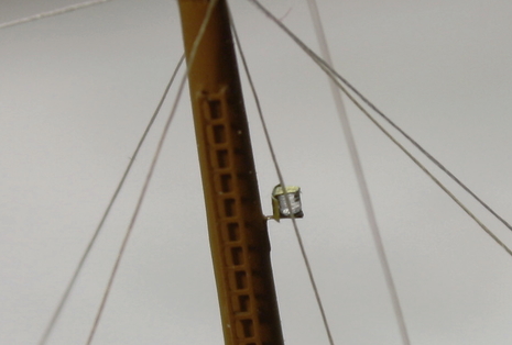
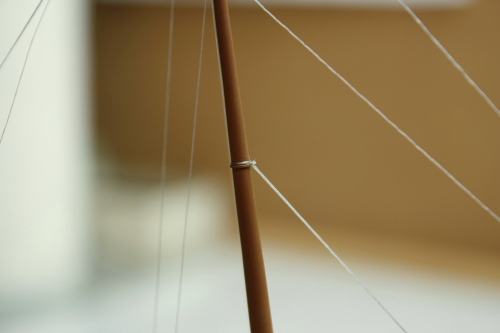
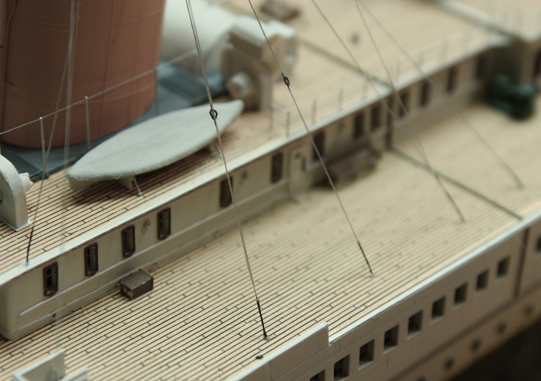
The challenge with brass masts (or masts made of any material, for that matter) is securing the lines in a manner that won't allow them to slide downward. (Most of the rigging is angled sharply downward from the masts). In the photo below right, note the ring around the mast just under the line; these rings replicated the bands called "hounds" that were on the real masts.
The real masts had bands, or "hounds", at each point where the rigging attached. These served as the points of attachment for the rigging hardware; After much experimentation, these were successfully replicated from spare photo-etched brass pieces. These rings would replicate the hounds on the actual ship and while the rigging would not be attached to them directly, they would prevent the attached lines from sliding downward along the masts when tensioned. Each was made from a square photoetched brass window with the mullions removed, then gently stretched and shaped into a ring of the correct diameter to fit tightly around the mast at the right points. Very narrow strips of photoetched brass might have worked also, curved to match the mast profile and affixed with CA cement, but the "ring method" used on this model doesn't depend on the holding power of the CA cement (and CA cement doesn't form a strong bond with brass).
The real masts had bands, or "hounds", at each point where the rigging attached. These served as the points of attachment for the rigging hardware; After much experimentation, these were successfully replicated from spare photo-etched brass pieces. These rings would replicate the hounds on the actual ship and while the rigging would not be attached to them directly, they would prevent the attached lines from sliding downward along the masts when tensioned. Each was made from a square photoetched brass window with the mullions removed, then gently stretched and shaped into a ring of the correct diameter to fit tightly around the mast at the right points. Very narrow strips of photoetched brass might have worked also, curved to match the mast profile and affixed with CA cement, but the "ring method" used on this model doesn't depend on the holding power of the CA cement (and CA cement doesn't form a strong bond with brass).
|
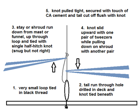
Once the hounds were in place, all the stays were secured to the masts before they were stepped (installed). A turn was taken around the mast and the line secured back to itself with a half-hitch, which was then tightened and secured with a dab of CA cement before cutting it off flush. The knot was then slid around to the desired point on the mast and pink CA cement wicked beneath the thread to keep it in the desired position. The line around the mast was then painted the mast color.
As noted above, the shrouds were not actually attached to the masts but were run through a hole drilled straight through, so the two shrouds for each mast are actually a single line secured at each end. |
|
A problem that took some time to solve was how the rigging lines would be tensioned. After experimenting with various methods on a prototype mast set up in a block of wood, a surprisingly simple method was found (below left).
|
|
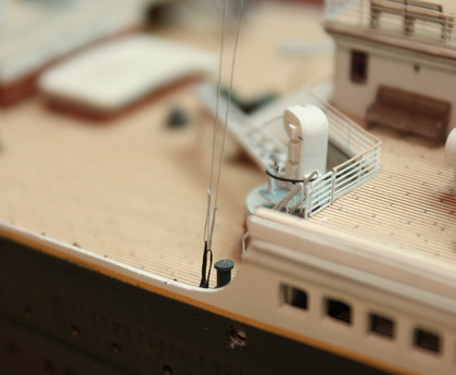
This method has the added benefit that the black loops of thread at the deck level, when they're under tension, resemble the rigging screws that secured the lines to the deck on the real ship.
|
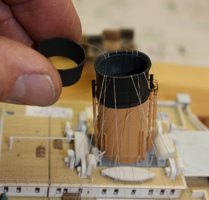
The same method would have worked for the funnel shrouds, but as rigging screws weren't used at the lower end, I did not want any knots at deck level. Instead, the shrouds were run up from the deck, into the funnels and out the tops. They were then tensioned with clothes pins and an inner collar of sheet styrene was inserted within. The collar was precisely sized to fit snugly and press the lines against the insides of the funnels. This maintained the tension and eliminated the need for any knots. The inner collars also served to replicate the inner walls of the funnels.
Below, the lower ends of the funnel shrouds were coated with yellow CA cement and painted black to simulate the black sheathing that covered these wire ropes near the deck. On the two shrouds in the center are the special links that were in place for rigging block and tackles for the purpose of raising the Englehardt collapsible lifeboats up off the deckhouse roof and down on to the deck, where they would then be connected to the main lifeboat falls and hoisted up and over the side. These were replicated with small photoetched eyes painted black. |
|
|
|
Before drilling holes for the funnel shrouds, the location of the davit frames and the portable railings inboard of the boats need to be marked on the deck. If the funnel shrouds are mounted even one or two plank widths too far outboard, they'll interfere with the placement of the davit frames and railings.
|
|
Right: halyards and other running rigging that ran through blocks on the stays were simulated by folding a piece of straightened thread back tightly back against itself, then pulled down over the top of the stay, one strand on either side. A miniscule drop of CA cement secured it, and a tiny application of paint in a neutral dark brown color completed the illusion of a block. Before pulling it gently taught and securing it on deck, it was twisted back on itself a few times near the top to prevent the two strands from coming apart. For the larger gin block on the cargo runner over the forward Well Deck, the strands were left apart. A 2-mm disc of photoetched brass was carefully cemented against the underside of the stay between the two strands and then painted dark grey to replicate the large gin block that was used for hoisting cargo.
|

|
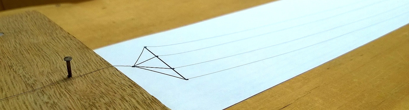
The Marconi array (the antenna wires suspended between the masts) was rigged before transferring it to the masts on the model. This was done on a jig on top of the model cover. Two pins placed exactly the same distance apart as the mast heads ensured that the completed array would be the right size once it was transferred to the model.
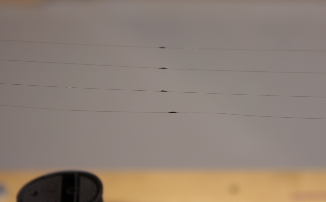
The silicon-bronze antenna wires were modeled with wire made of a nickel-titanium alloy called Nitinol. It's perfectly straight and won't kink from handling. Equally important, it's available in the correct scale size. I used wire of .047mm (less than .002") which is 5/8" diameter in scale - exactly what it should be. It's incredibly fine, no thicker than an individual strand in a spiderweb- so fine, in fact, that it's very difficult to see the antenna wires from a foot away without a light color in the background.
I had originally purchased Nitinol that came with a gunmetal blue/black finish, and was intending to use that even though the color wasn't accurate for the Marconi wires. But only a week or two before rigging the array I stumbled across a brand called "Modelkasten" which has a brown finish - perfect for its intended application. (Modelkasten is a Japanese brand sold for modeling the rigging on scale WWI- and WWII-era naval ships.)
At each end of the array, as seen in the photo above, the wire/rope spans were kept apart by an ash spreader held away from the mast with tarred hemp lines. One of the sheets of photoetched brass from Tom's Modelworks has two of these spreader assemblies. These are very fine pieces and the sections replicating the ropes are just as fine as thread, so I elected to use them to avoid making my own which would have had visible knots.
|
On the Olympic-class ships, the silicon-bronze Marconi wires did not span the entire distance between the masts - they had to be a specific (shorter) length in order to be the correct length for shortwave transmissions. The remaining distance was spanned by tarred hemp ropes that connected to the after end of the antenna wires about 135 feet from the spreader . I elected not to use fly-tying thread to model these since the finest available in the proper color would have been many times thicker than the Nitinol and would have compromised the overall appearance of the array. I used Nitinol for the entire spans, and replicated the insulators between the tarred hemp and the Marconi wires with Elmer's glue recoated with yellow CA cement and painted black.
|
MODELING RESOURCES - Rigging material used on this model_________________________________________________________
|
STAYS, SHROUDS, CARGO SPAN AND CARGO RUNNER - UNI flyting thread 8/0 Gray
SIGNAL AND FLAG HALYARDS - UNI flytying thread, 8/0 Tan
MARCONI ARRAY - UNI flytying thread 8/0 Iron Gray for the tarred hemp lines aft, .003" Nitinol for the aerial wires
|
|
MODELING RESOURCES - Click for links______________________________________________________________________________________
|