|
The lifeboats and davits presented some unique challenges, from simulating the canvas covers to replicating the davit blocks and their rigging. From the beginning I was determined to use individual lines of thread instead of photoetched brass ropes, as I wanted all the falls (lowering lines) to be scale accurate in size and appearance to an observer regardless of how closely seen. Complicating things was the inescapable fact that many of the lines had to be rigged to the davits before they were installed on the ship, since it would be impossible to rig lines to the sides of the davits facing inward after they were on the ship. As with so many other areas of this build, it came down to figuring out what would work and how to accomplish it.
|
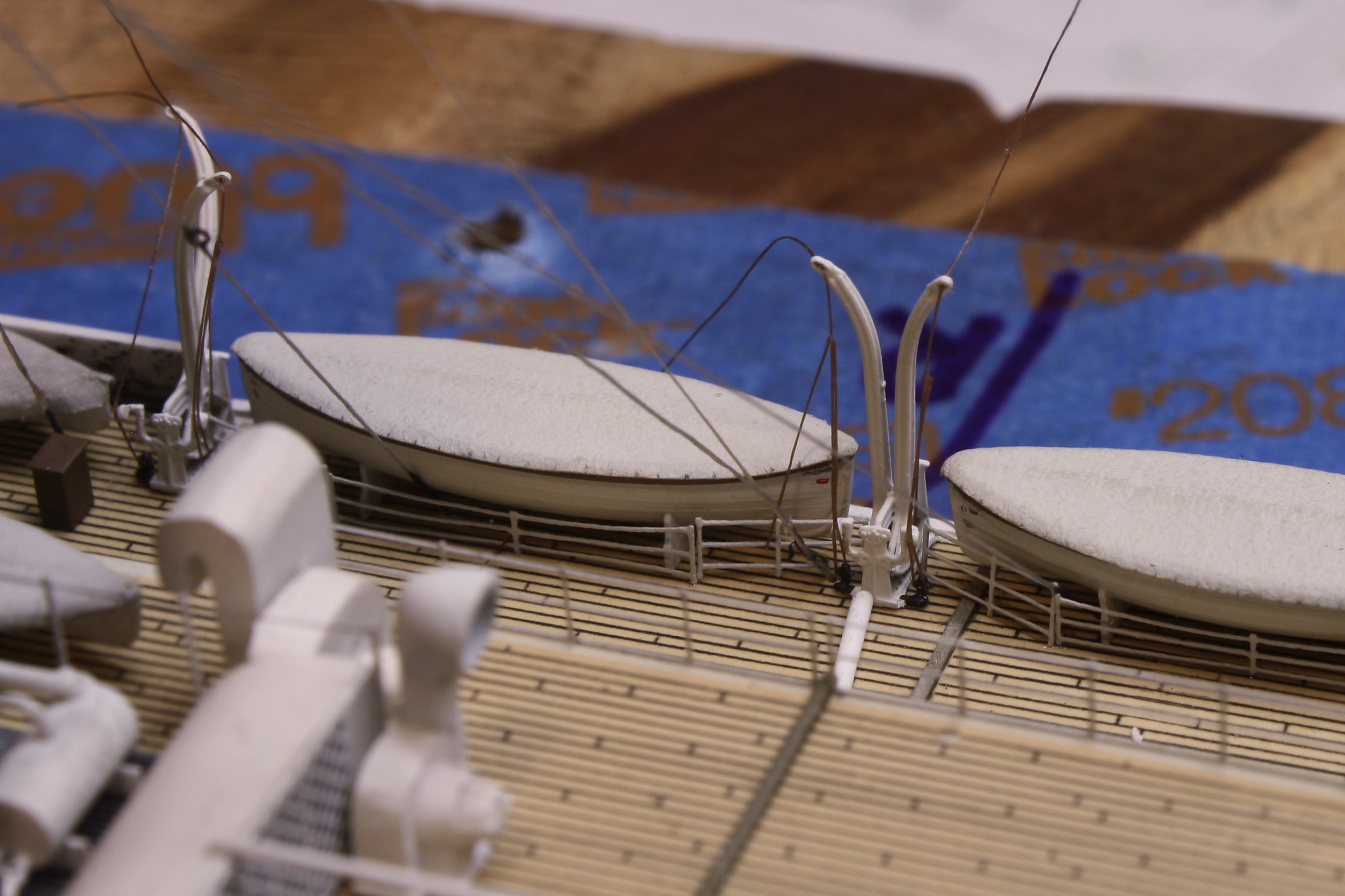
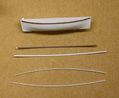
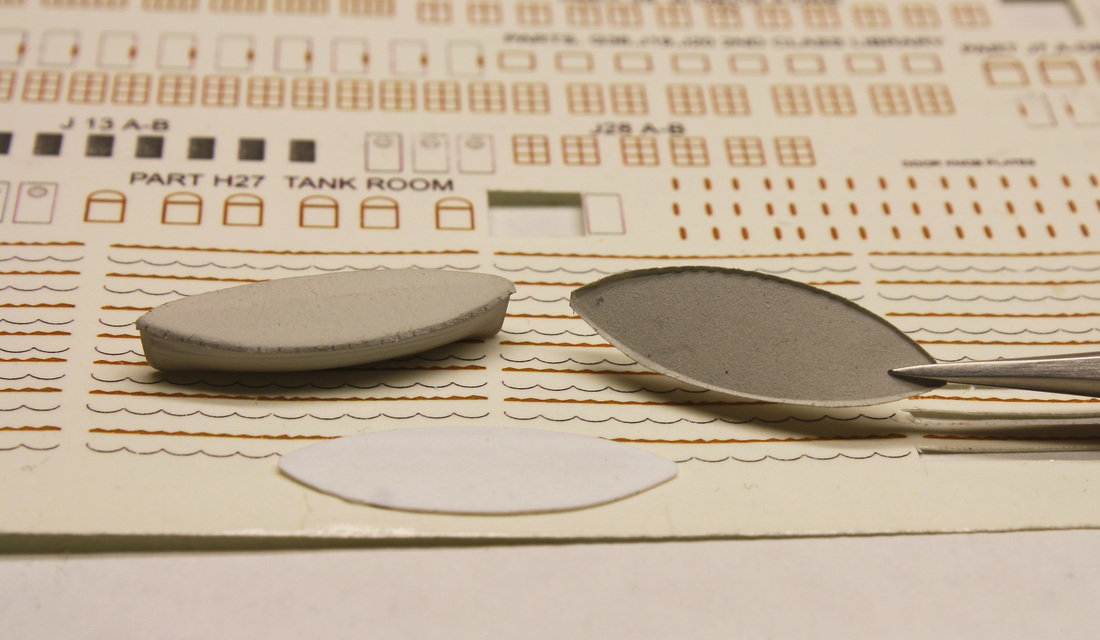
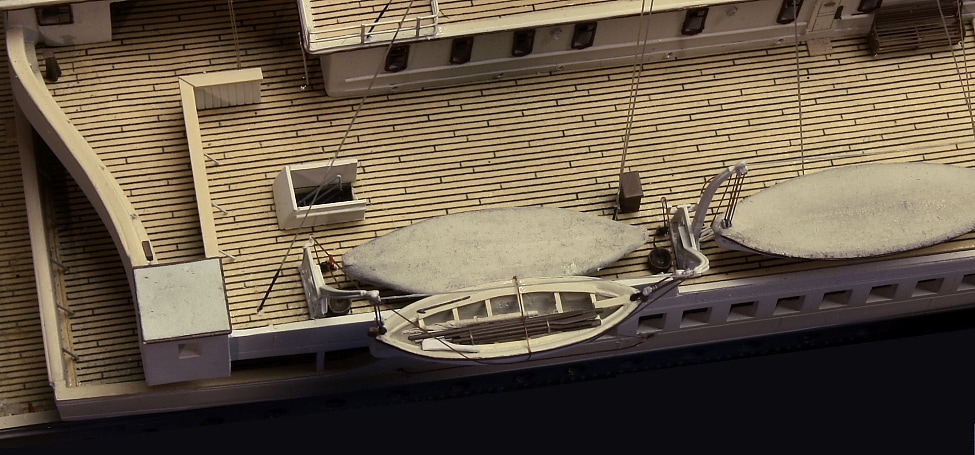
The lifeboats were detailed by adding brown gunwales* made of painted .005" styrene strips. The 30-ft main lifeboats had canvas covers; these were cut from an ordinary newspaper (I used the page edges with no print on either side.) When airbrushed a dirty off-white color, the rough texture that resulted was perfect for simulating canvas. Copy paper instead of newsprint was used for the covers on the collapsible lifeboats and the cargo hatches in the Well Decks; that was before I thought of trying newspaper. Newspaper worked especially well for the lifeboats because it was thin enough to bend over the top edges of the gunwales (using a template) by a very slight margin. *Olympic's were white, but Titanic's were brown.
The grommets and tiedowns along the edges of the covers were replicated by marking them with a very sharp No. 6 draftman's pencil, and then painting over the markings with a diluted wash of canvas-colored paint.
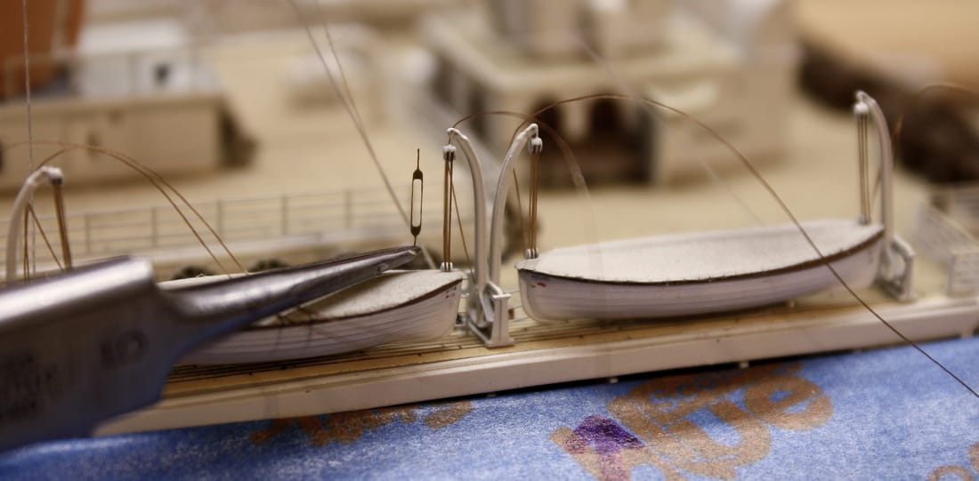
The 25-ft cutters (the two forward-most boats) were referred to as "emergency boats" and were kept uncovered and swung out in case someone fell overboard. Because they're open and highly visible, the interiors had to be hollowed out and detailed. Side benches, thwarts, gangboards and clamps and steps for the masts were added, and each cutter was equipped with a mast, sail, rudder, oars, boat hook, painter (tow line), water breaker (cask) and crutches for the ridge pole. One of the photoetched brass sets for Titanic includes oars for these boats, but the blades are the wrong shape and the shafts are too thick for scale. New ones were scratchbuilt from .010" styrene rod heated near a soldering iron and pulled to .005" diameter, with the blades formed by crimping the end of the rod in the flat jaws of a small pliers. Some final trimming with an X-Acto knife is all that was required to create 12 identical oars. (To give an idea of the scale, each cutter in the photo below is only 7/8" (22 mm) long.)
The rolled-up sail was made with newsprint, airbrushed on both sides and then rolled and tied. The masts were made from styrene rod sanded to give then a slight taper, and the water breakers were cut from .035" styrene rod and then rolled between a thumb and sanding pad to taper the ends. The boathooks were made from the hair off one of my Labrador Retrievers' tail.
The lifeboat marking plates* are available as decals from the kit, but these weren't used as even the ones from an older kit - which are slightly smaller than the ones from the newest kit - are too large for scale. Instead a very sharp draftsman's pencil was used to make similar markings at the same locations. The White Star Line flag was made with a very tiny stroke of red paint with a fine-tipped brush. At 1:350 scale all of these markings would have been impossible to read, so replicating them exactly was not required. * Ship's name plates, home port plates, company flag plates, number plates and load plates.
|
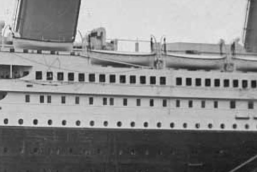
The grab lines (loops of rope hanging below the lifeboat gunwales) were not added. The only "stock" methods of modeling them- decals and photoetched brass - proved unsatisfactory; the decals looked like decals and the P/E brass was too thick and stood out too much. Loops of fine thread were tried, but expecting to get them uniformly sized and spaced on 28 separate boat sides would have been unrealistic. In reality the grab lines were not readily visible, as evidenced by the photo at left of Olympic departing Southampton. Despite the fairly close vantage point of the photographer - the equivalent of viewing the model from about 15" away - the grab lines can barely be seen. Given how they appear in this and other photographs, I believe leaving them off was the right decision. |
|
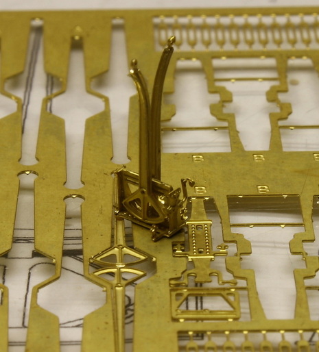
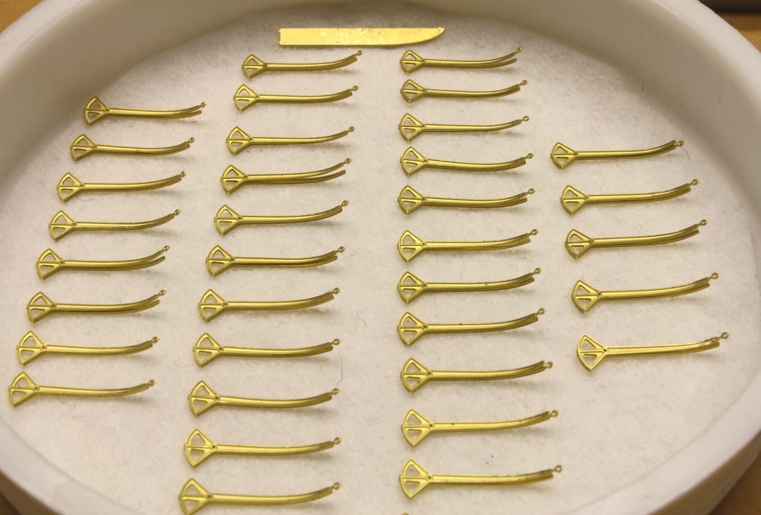
The Welin davits were replicated with photoetched brass ones from Gold Medal Models. The davits themselves are cut from the sheet and then folded back on themselves so that the photoetched relief shows on both sides.
One other manufacturer offers these, but in my opinion the GMM version is superior because of the three-dimensional detail etched into the components. The GMM version also makes assembly of the davit frames easier because they're in one piece and simply fold up into shape. |
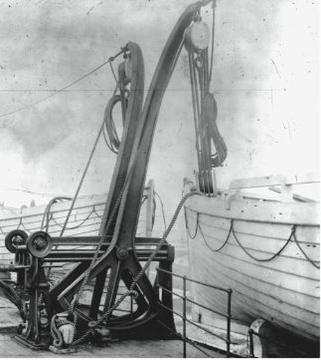
In the photo above right from the Welin Davit Company, the davit frames and arms are painted black. They were white on the Olympic-class ships. The ones in the photo also have coils of rope tied to the falls; on Olympic and Titanic they were secured out of sight beneath the canvas covers (not shown)
To curve the davits, a jig was used based on a prototype made by modeler Dave Abate. It was constructed of built-up styrene with the davit curve filed into it. When it closely matched the davit template from the photoetched brass sheet, the template was then gripped tightly in a small pair of pliers and scraped back and forth in the jig to transfer the exact curve of the template to the styrene plastic. An upraised ridge was then cemented to the jig for the base of each davit to butt against while being shaped.
|
The davits were bent by placing them in the jig, first pressing them gently into the curve with the handle of an X-Acto knife, and then a metal rod was rolled more firmly against the davit to give it the final curve. (A stainless steel rod was used, but one of brass would have worked just as well.)
The davit eyes were bent after holding the end of the davit against the tip of a hot soldering iron. The davits were then returned to the jig and given final corrections as necessary (in case any were inadvertently bent during handling) and then pink CA cement wicked between the folded halves. As with any fitting produced in quantity, more were made than necessary so that the imperfect ones could be discarded. |
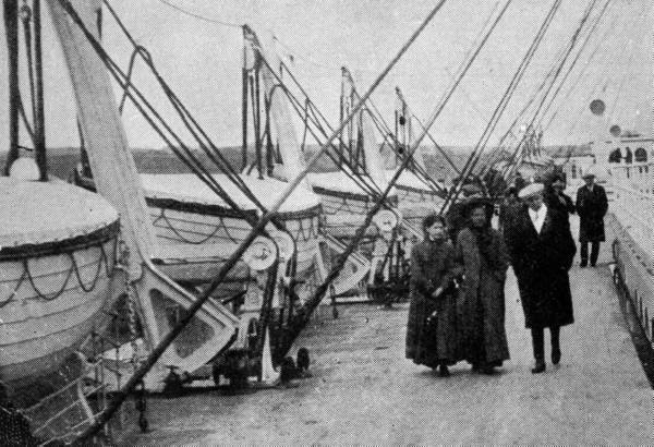
On the assembled davits, the arms are not vertical. With Titanic's boats in their normal inboard positions on deck the arms were angled slightly inward from the vertical.* The exception was the arms carrying the cutters, or "emergency boats" (the two forward-most boats directly opposite the Navigating Bridge). These were swung fully outboard once Titanic was at sea.
* Photos show that at sea and in port, the davit arms for the after set of boats on each side were cranked partly outboard in order to shift the boats further out on the deck, as seen in the photo taken at Queenstown below. This increased the space for promenading. It's generally accepted that the boats were shifted inboard while entering port in order to give the ship's officers a clear line of sight aft from the wing cabs of the Navigating Bridge. It's unknown whether this was done when Titanic entered the harbor at Cherbourg, but in accordance with what seems to have been standard procedure I elected to model mine in the upright positions.
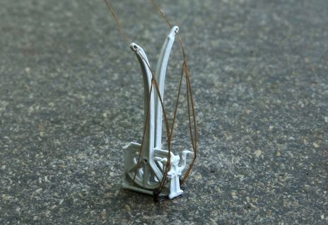
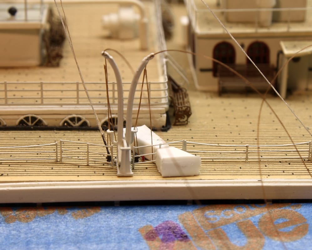
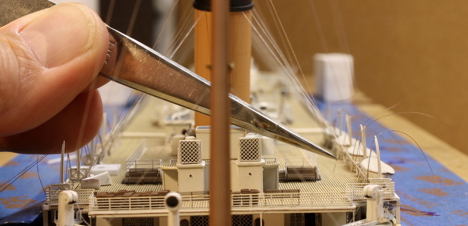
Figuring out how to accurately replicate the lifeboat falls (lowering lines) was an exercise in patience. From the upper block that hung from the davit arm, each fall ran down to the sheave (pulley wheel) on the davit frame and then to the bit on the deck. The line then took several turns around the bit and was led back up along the fall where it was tied off most of the way up, then it dropped down into the lifeboat where it was coiled and stored in a wooden tub. Ultimately, the solution was not attempting to use one continuous piece of thread. Before the davits were mounted to the deck, all the sections of line on the inboard side of the davits were added (below right) since it would have been too difficult to accomplish this after they were in place. The blocks and lines hanging below the davit arms, and the wire rope spans between the davits, were added after the boats were installed.
Note: in the photo of the completed davits at right, the upper ends of the falls have been passed through the davit eyes. This was only temporary for holding the lines upright until the final rigging was complete. These lines would be run directly to the blocks when they were installed later, as seen in the Queenstown photo. Also note that the davit arms in the Queenstown photo are in their outboard positions, whereas mine are modeled in the inboard positions as noted above.
|
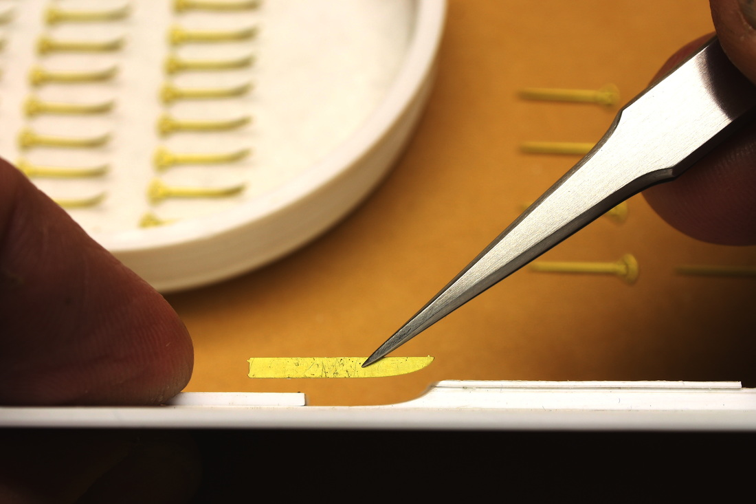
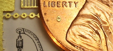
One dilemma that took a long time to solve was figuring out how to realistically model the blocks and lines that lowered the lifeboats. Photoetched brass ones are available (held in the tweezers for comparison in the photo below), but I didn't use them because they're one dimensional and don't look realistic up close. They're also the wrong length. Instead, I built my own blocks using very small discs cut from a photoetched brass Lifeboat Davits sheet from Tom's Modelworks*. Using a 3200-grit sanding pad, I reshaped them to oblong shapes (right).
|
These were dipped in white paint and allowed to dry. They were then assembled** with precut sections of thread made rigid with CA cement and treated with DulCote to eliminate the shine. Except for the cutters, one of each set was made as a half-block (below) because the lower blocks of the 30ft boats only had their upper halves visible where they stuck up through the canvas covers.
* As noted in the text describing the davits, I chose to use photoetched brass davits from Gold Medal Models. I only used the gripes (tie-down chains) from Tom's
Modelworks, which allowed me to use the the discs in the above photo for other than their intended purpose.
**The jig used to assemble these component is shown near the end of the Benchwork page.
Modelworks, which allowed me to use the the discs in the above photo for other than their intended purpose.
**The jig used to assemble these component is shown near the end of the Benchwork page.
Above, the block-and-fall assemblies installed on boats 14 and 16. Held in the tweezer is the photoetched brass alternative that I chose not to use. The blocks on the real Titanic had three sheaves and six lines running between the blocks, but I built mine with only two sheaves each because using three would have made them too wide and out of scale. You can't tell the difference without magnification and the visual effect is no less impressive.
|
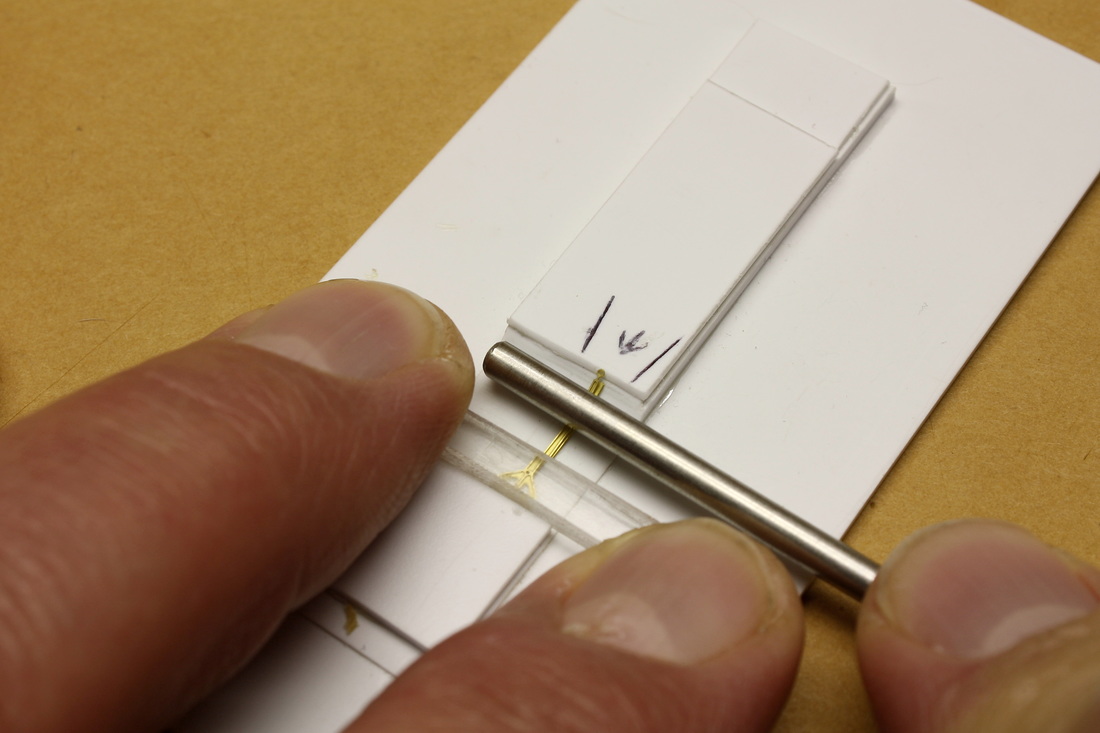
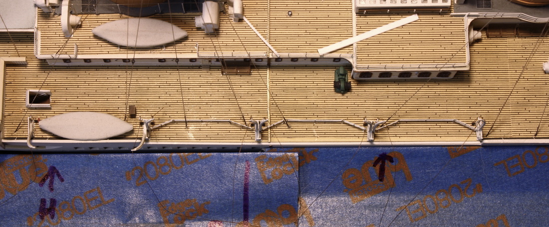
Before the boats could be installed, the portable railings had to be put in place. These railings prevented passengers and crew from slipping underneath the boats in wet weather and/or rough conditions. Here they were positioned upright between two pieces of styrene and shifted until they were exactly in the right spot and then cemented in place. (See the end of the Benchwork page for the tool & technique used. )
Below, the railings at the forward set of boats on the port side, ready for the 30-ft lifeboats. The blue painter's tape, folded over and stuck back to itself where it touched the ship, covered the gap between the drydock lid and the edge of the ship to prevent small pieces from falling down into the box if they were accidentally dropped while handling. The arrows on the tape mark hydrant locations, and the vertical line marks the future location of the railings that separated the 1st Class Promenade from the Officers' Promenade. |
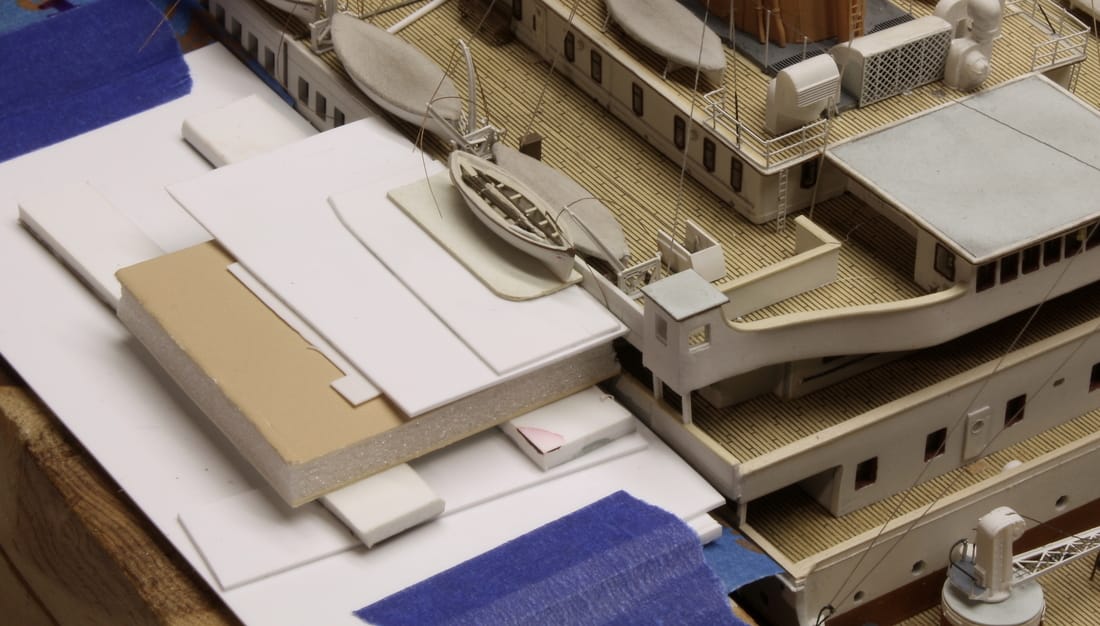
Below left, a temporary chock was filed from rectangular tubing to support the outboard half of each lifeboat while it was positioned in place. Because the chocks under the lifeboats only supported boats on the inboard sides, the boats on the model wanted to tip over when stood upright. Like the railings in the photo above, they could not be cemented directly in place because they had to be centered precisely between the davits and lined up fore-and-aft first. Then it was cemented to the deck by applying a small amount of CA cement to each chock.
The cutters were installed last. I considered suspending them from the davits, but decided on a more secure arrangement. Since the lower strakes (planks) of both rested against the top of the bulwark, I shaped a small, narrow rib of styrene plastic to match the curve of the boat just above the point of contact with the ship. The rib was cemented to the cutter and then to the top of the bulwark. The cutter was thus solidly attached to the ship, although it didn't appear to be. The point of attachment can't be seen because it's hidden between the cutter and the collapsible lifeboat on the deck adjacent.
Installing the gripes (the chains that secured the lifeboats to the deck) required a steadier hand than almost any other work on the ship. After trying various methods, the only way I could place them accurately and symmetrically was to reach through the rigging from the other side. Doing this while holding the tweezers so far back from the points required was very difficult.
After the gripes were installed, the block-and-fall assemblies were put in place between the boats and the davits. These were rigid and required no tensioning; they were simply secured to the davits and the boat covers with CA cement.
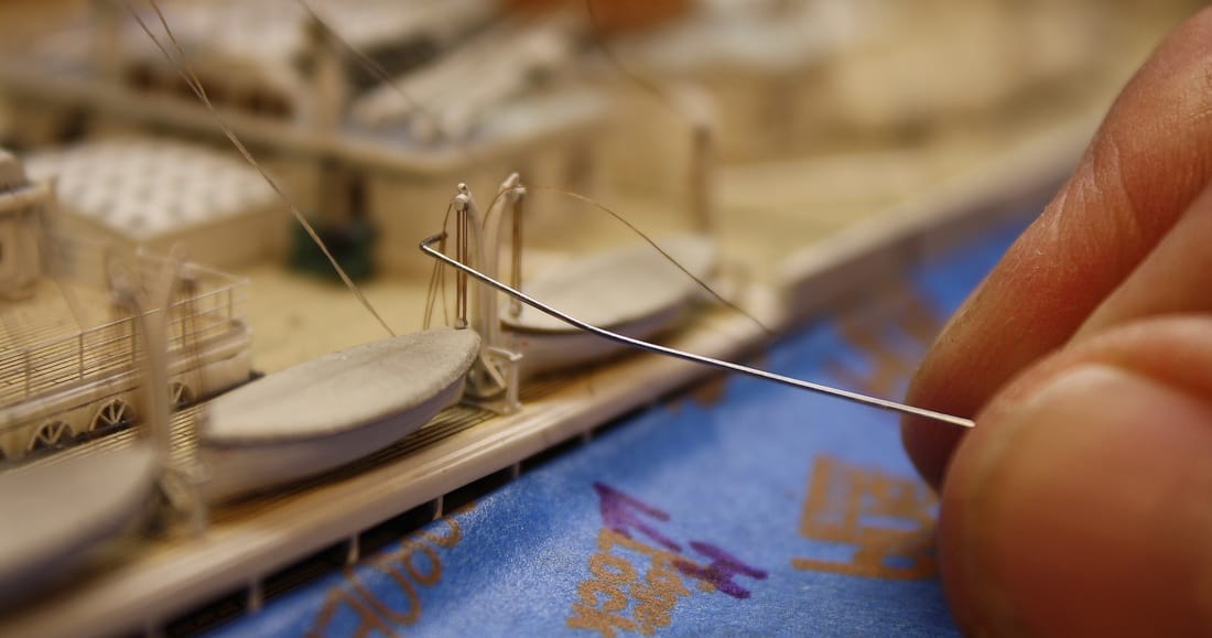
The final step to complete the rigging was to attach the pre-rigged lines on the davits to the upper blocks. Below right, a hooked wire is being used to bring the tip of the line into contact with one of the sheaves on the upper block after cutting off the excess thread and applying CA cement to the tip. The other end of this line, hanging down from where the tip of the wire is touching, will be run up and under the edge of the lifeboat cover.
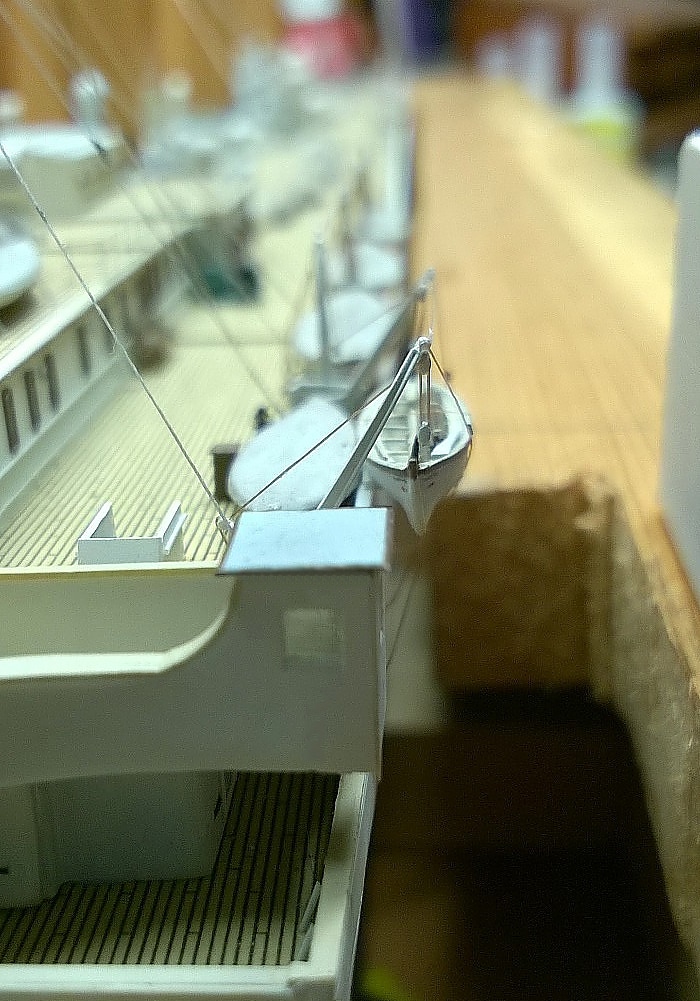
The falls for the cutters had to be done differently. Because the davits were cranked fully outboard and the cutters were suspended from them, the falls had to appear taught. But the lines couldn't be tensioned as they would break the davit arms off the frames. To work around this, for each davit a section of thread was made rigid by an application of CA cement, cut to length and cemented in place between the davit roller and the block. As with the main 30-ft lifeboats, the falls appear to be continuous lines but are actually applied in separate sections joined so carefully you can't tell.
Octagonal tubs for the cutters' falls (below) were made from styrene rod of the appropriate diameter, then drilled out and painted with a color to simulate rope. A short section of rope was led into each tub from the bit at the base of each davit frame.
The final step was to rig the wire rope spans between the eyes at the ends of the davit arms. These were made with the same 8/0 fly tying thread used for the rigging. They were made semi-rigid by heating and straightening them, and then coating them with fast-drying CA cement followed by a coating of DulCote to remove the gloss. They weren't knotted, just cut to the exact length needed and secured in place with the lightest touch of CA cement.
|
The threads that will be used for the outboard gripes for the cutters (the three crossed lines that secured the cutters against the bulwark) need to be drilled through the A-Deck screens before they're installed. Otherwise when it's time to rig the gripes, there will be no way of attaching them to the side of the superstructure.
|
