|
The kit used as the basis for this build was the 1:350 scale Minicraft Titanic. The Minicraft is generally regarded as the most accurate Titanic kit available and has the potential to be turned into a museum-quality build once some of the heavier parts are replaced with more detailed alternatives. Initially I just intended to spend 3-4 months assembling and painting an out-of-the-box kit, but as the build progressed a new goal slowly evolved: to build a model of the ship that was not only historically accurate in every regard, but to a level of detail that's normally seen only in much larger scales such as 1:144 and above. As time went on, I found myself working to more and more exacting standards and making increasingly smaller fittings to replace the kit pieces.
|
|
Although I may have achieved levels of detailing beyond what's ever been done at this scale, it wasn't to break any records or to better anyone else's work. There are other impressive builds out there by modelers like Morten Jensen, Jason King and others who are superb craftsmen in their own right. There are no comparisons on this website with theirs or any others. This model was a personal best and nothing more.
|
About these pages - Although this website is not a tutorial or step-by-step build log of this project, it does show how much of the detail work was accomplished and what was done to make this a museum-quality build. It also includes modeling references you can download and links to suppliers for those wishing to duplicate some of what was done here. If you're a modeler looking to enhance your own build, it's for you to decide what's within your skill level - or what's worth reaching for. |
Detail and accuracy weren't the only considerations. This wouldn't be a "builder's model", mounted on a stand to show the ship above and below the water in pristine condition. This ship would look realistic. That would mean adding dirt, grime, rust and weathering in the appropriate places to reflect her time in service, however brief.
Step One was to transfer all the required modifications and enhancements onto a set of detailed deck plans and elevation drawings. The model's lighting systems also had to be incorporated into the planning and the deck lamps drawn in. Below is a section of the Hahn Titanic plans used for this model. This detail shows the Officers' Quarters deckhouse. The number of changes and enhancements handwritten on this one area alone illustrates how much work was done to convert the kit to a fully detailed and historically accurate scale replica. The planning stage took about a month in late summer/early fall of 2003.
For more on the changes made to make this model fully accurate for Titanic, see the page Achieving Historical Accuracy.
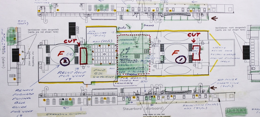
Plan detail used by permission of Robert Hahn.
MODELING RESOURCES - Click for links______________________________________________________________________________________
|
Cutting a perfectly good hull in half may seem like an odd thing to do, but since this would be a waterline model replicating Titanic just after her arrival in Cherbourg harbor it was a necessary first step. Early on I decided on a waterline model (simulating the ship as she appeared on, rather than out of, the water) because I wanted to replicate Titanic as people actually saw her. In addition, I wanted an illuminated model ever since I saw Ken Marschall's iconic painting of Titanic in Cherbourg Harbor just after sunset. From the start, this was how I wanted to portray her - right down to the exact portholes and rooms lit up in the painting.

Heavy-duty styrene braces were cemented athwartships to give the hull rigidity and to provide support for the lighting components. More than a month was spent enhancing the hull detail by re-scribing the lines of the shell plating and hull doors, adding doors for the missing coaling ports and numerous small fittings that were not part of the kit - as would be done throughout the build. Overall, the Minicraft hull piece is exceptionally well detailed to start with, so the result was all that could be asked for and then some.

Elevation drawings at top of image from Hahn Titanic Plans. Used by permission of Robert Hahn.
Sidelight diagram at bottom of image by Frank Giaccobe. Used by permission of TRMA.
Sidelight diagram at bottom of image by Frank Giaccobe. Used by permission of TRMA.
In addition, all the portholes were drilled out to the correct scale diameters. After painting the hull, brass paint was carefully applied to the inside edges to simulate the sidelight frames that held the glass. Later, the glass in the sidelights was replicated as outlined on the Lighting page. Significant modifications were also made to the interior deck pieces for light distribution.
Very few photos were taken during the initial stages of the build because I never anticipated that the project would expand to involve so much time and detail. Only after the outer decks were in place did I realize the need to record step-by-step progress.
Very few photos were taken during the initial stages of the build because I never anticipated that the project would expand to involve so much time and detail. Only after the outer decks were in place did I realize the need to record step-by-step progress.
MODELING RESOURCES - click for links______________________________________________________________________________________
At this point it should be explained that the instruction manual for the model kit was not followed for this build. Most of the assembly is common sense and takes place in a sequential manner, but it's not essential to do much of it in exactly the order laid out in the manual. For example, the Forecastle Deck was completed except for the railings before work proceeded on any other area of the upper decks.
At this point it should be explained that the instruction manual for the model kit was not followed for this build. Most of the assembly is common sense and takes place in a sequential manner, but it's not essential to do much of it in exactly the order laid out in the manual. For example, the Forecastle Deck was completed except for the railings before work proceeded on any other area of the upper decks.
|
Modeling Titanic at Cherbourg - Modeling Titanic as she appeared at Cherbourg wasn't just a matter replicating the illuminated rooms and compartments that Ken Marschall portrayed as such in his painting. There were several large stacks of folded-up deck chairs that were moved to different locations during the first two days of the voyage, along with two deck benches that were moved to accommodate them. Some of the rigging for cargo handling also changed after Cherbourg. |
Deck planking decals were used to replicate the lines of the yellow pine and pitch pine used on the real ship. Wood veneer decks with scale-accurate plank widths were not commercially available when this kit was started, but even if they had been I wouldn't use them. The concept is great, but they're not available from either of the current manufacturers in maple or another hardwood which is lighter in color and has a really fine grain. More critically, there are inaccuracies with some ventilator locations on both that would be difficult to fix, plus neither has the raised roof over the 1st Class Lounge and Reading & Writing Room correct for Titanic. If they offered them in hardwood, and were correct all around, then I might wish I had them available at the time. The deck planking decals I used, as far as I'm concerned, give a very satisfactory appearance and are superior in some aspects.
|
Before painting the wood color that would show under the decals, the ridges cast into the kit pieces to simulate planking lines were removed and all deck surfaces were sanded smooth. The paint color was a difficult choice as I found the decaled plank lines affected the overall appearance of the color. With the decals applied, the black planking lines made the color look much less tan. A lot of colors were experimented with.
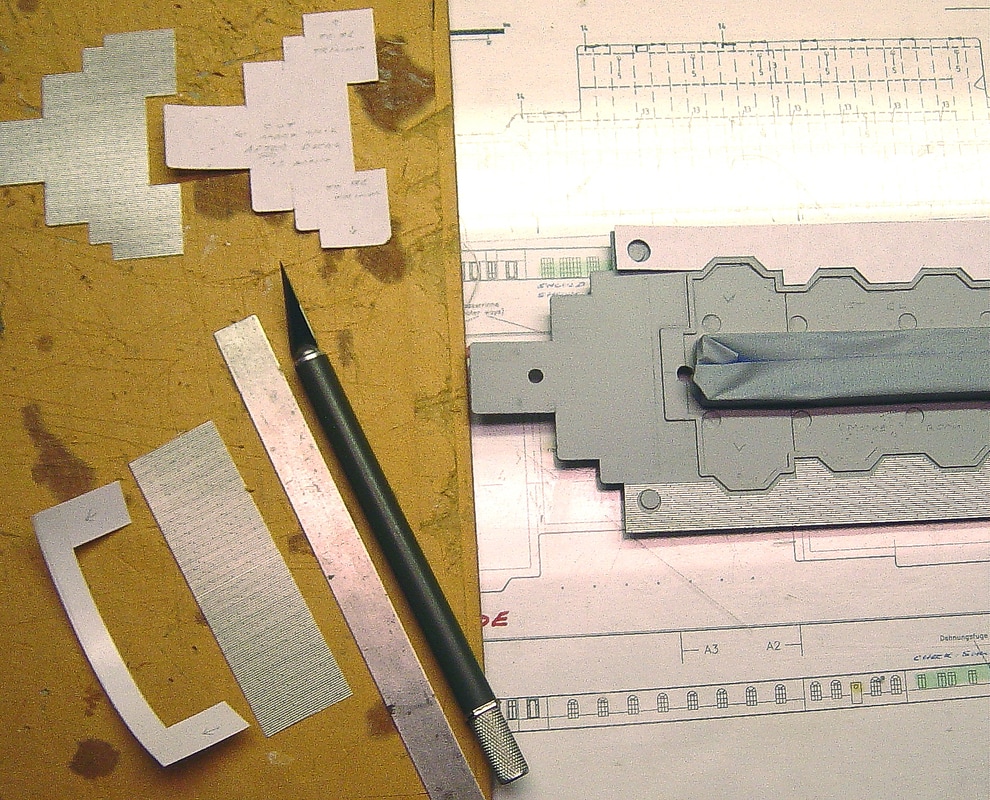
Before cutting the decals, paper templates were made to ensure that the decals would be a perfect fit around and inside all corners, bays and alcoves. MicroSol and MicroSet were used to help the decals conform tightly to the decks over any slight imperfections in the surface. Deck plan detail at top of image from page 84 of RMS Titanic: A Modelmaker's Guide by Peter Davies-Garner. Deck plan and elevation detail at center and bottom of image from Hahn Titanic Plans. Both used by permission . |
|
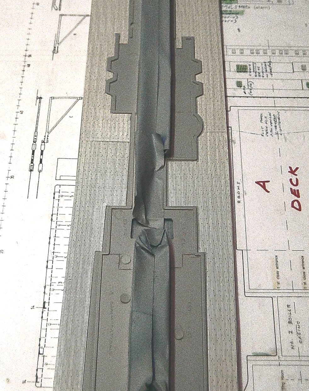
For the Promenade and Boat Decks, one problem was that these decks required three sheets of decals butted end to end. The challenge was making these decals meet so that the lines and pattern of the planks continued seamlessly. The Boat Deck in particular would be highly visible and the slightest imperfection would ruin the visual effect.
|
|
Deck plan detail and drawings at left of each image from page 84 of RMS Titanic: A Modelmaker's Guide by Peter Davies-Garner.
Deck plan and elevation detail at right of each image from Hahn Titanic Plans. Both used by permission.
Deck plan and elevation detail at right of each image from Hahn Titanic Plans. Both used by permission.
Scratchbuilding (referred to throughout this website) is the process of making something from scratch, as opposed to using a pre-made kit or aftermarket part. Items can be made and/or cut from standard model-building materials like styrene plastic or brass strips, sheet or rods, or from more unusual materials. Sometimes the right material is just waiting to be discovered, such as the glass wristwatch crystals that were used on this model to replicate the skylight domes over the grand staircases.
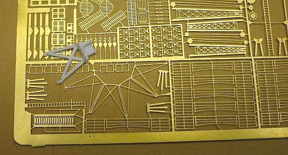
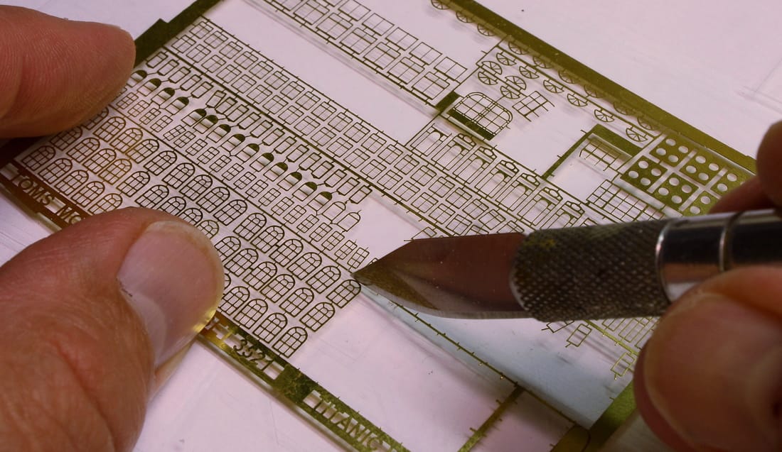
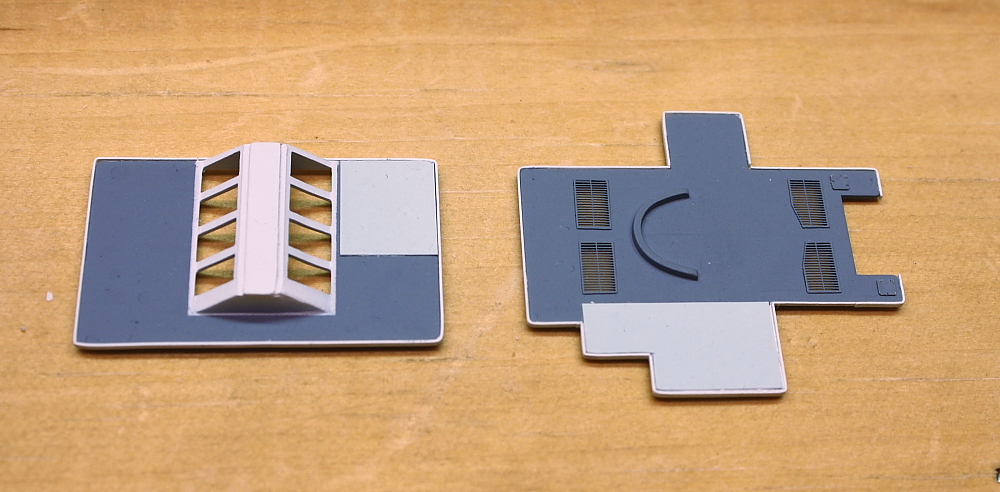
Cast styrene parts that were too thick or heavy could, in many cases, be replaced with photoetched brass parts. These are made from very thin sheets of brass. Various sets are available for specific ship models, and eight are specifically made for the 1:350 Titanic. kit (Two more sets are no longer available). By using these it's possible to achieve a level of detail far beyond the basic kit. Below is part of the compass tower sitting atop its photoetched brass equivalent: the difference is clearly apparent. P/E brass was also used for all the deck chairs, benches and railings on the ship; these are shown on the Fine Details page.
|
Photoetched brass sheets from different manufacturers were used, even where a sheet from one duplicated some of the parts from another. In some cases the parts from one are slightly more detailed or more accurately sized than the parts from another, and having both sets allowed the best to be used. In many cases, having more than one of the same sheet allowed for mistakes and discards. Leftover parts also provided a source for stanchions and other extremely fine stock for scratchbuilding other details. Countless details were made in this way from leftovers.
|
MODELING RESOURCES - Click for links______________________________________________________________________________________
|


The use of photoetched brass is the norm with serious modelers; nearly all use at least some P/E brass to take their model closer to a museum-quality build. However, photoetched parts can only replace some of the parts in the kit, and on this model replacements for all of the heavier three-dimensional fittings - bitts, capstans, etc - had to be manufactured. (See the page on Fine Details for those and for more on photoetched brass details.)
|
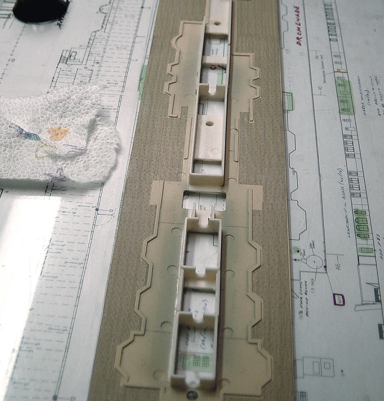
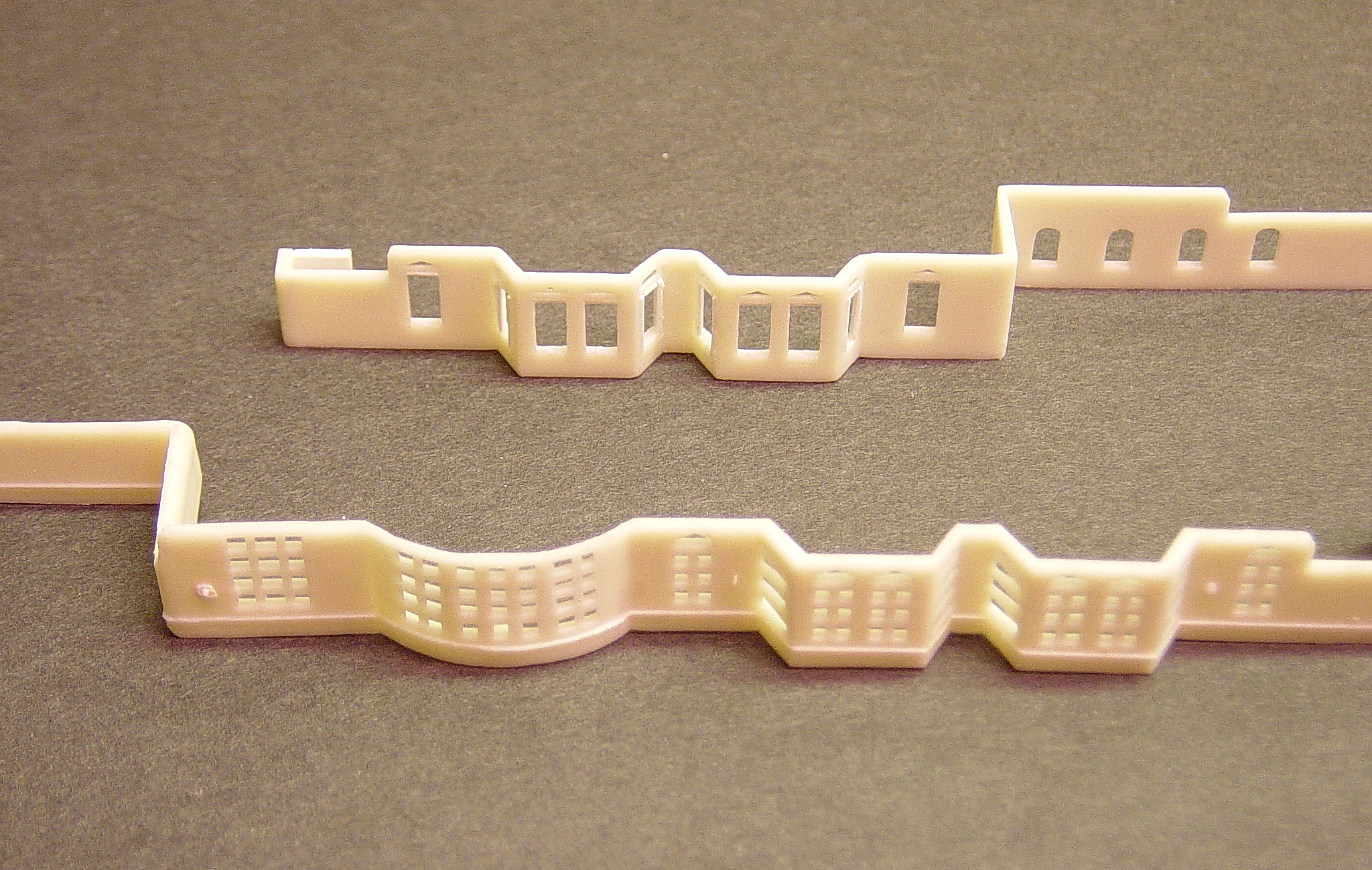
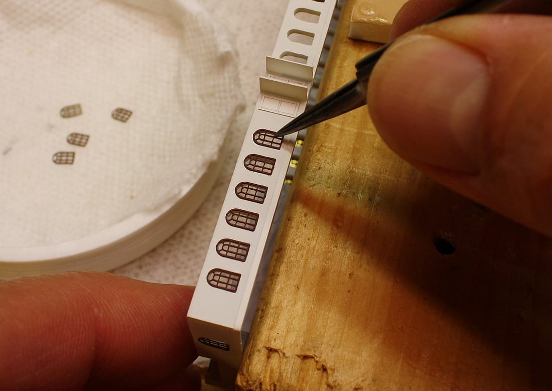
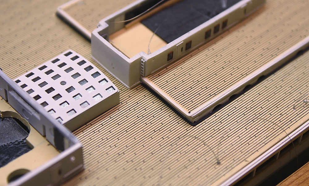
The windows cast into the bulkheads (walls) of the upper decks could also be replaced with scale-accurate ones of photoetched brass, but would first require a significant amount of modification. This work was a major part of the detail enhancement. At right, the bulkhead in the foreground is the kit part with the window mullions molded into the plastic. Prior to painting, all these had to be cut out and the openings enlarged to accommodate the photoetched brass windows. The bulkhead in the rear has had all the mullions removed and the openings carefully cut and trimmed to size. All the doors, decklamps, ladders and handrails cast into the piece have also been sanded off as they would be replaced with more detailed ones.
|
|
MODELING RESOURCE - Click for link______________________________________________________________________________________
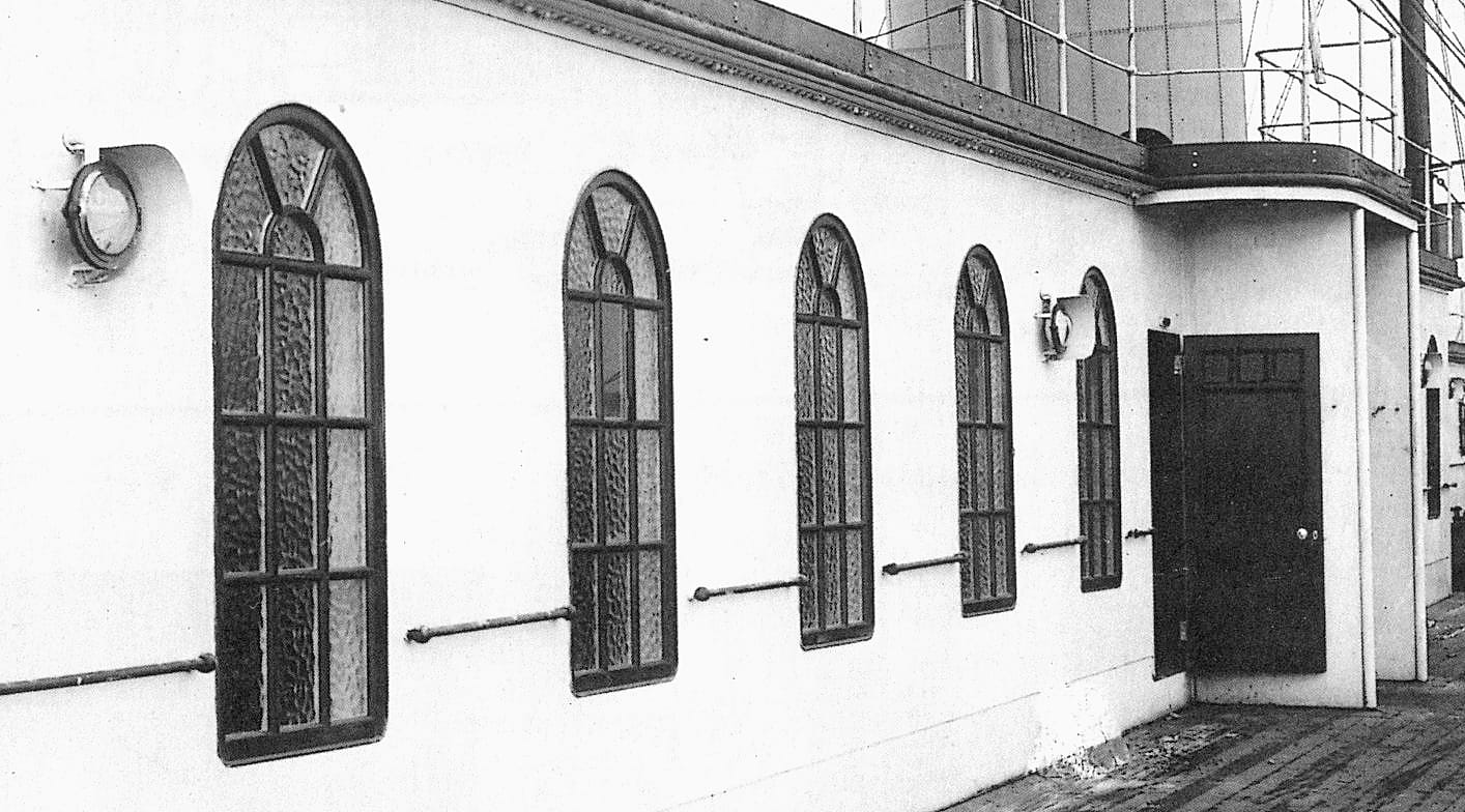
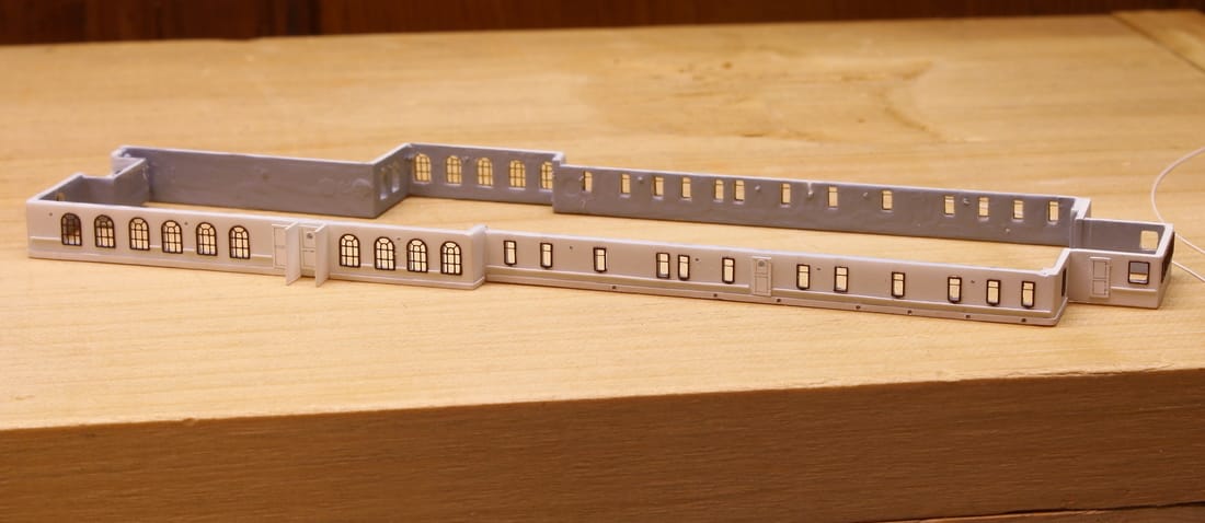
Below, installing the windows on the 1st Class Gymnasium. The openings had to be precisely resized to be large enough so the edges would not be visible behind the windows once they were in place, but not too large - otherwise, light would show from behind the outside of the frames (or the brass window would settle into the opening).
The doors are made from thin styrene sheets with the panel and trim lines drawn on with a No. 6 draftsman's pencil; the vertical doorknob guards have not been painted on yet to the ones in the photo.
The doors are made from thin styrene sheets with the panel and trim lines drawn on with a No. 6 draftsman's pencil; the vertical doorknob guards have not been painted on yet to the ones in the photo.
Any model kit with cast styrene parts makes assembly convenient, but at a trade-off: on close inspection, slight gaps will be visible between some of the larger pieces such as walls, roofs and deck pieces. Since it was impractical to rebuilt all of these from scratch, any imperfections had to be concealed. In most cases, any seams that remained visible at corner joints were filled with Mr. Surfacer (described in the Lighting section). White styrene putty was also extensively used where larger gaps were visible, then finished afterward with Mr. Surfacer. The goal was to eliminate all visual evidence of joints anywhere they appeared.
|
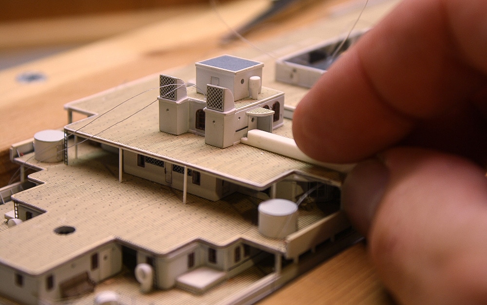
Not all seams or gaps could be eliminated in this manner. Typically, a very narrow seam remained visible at the base of most of the deckhouse walls after installation. To conceal these gaps, very thin, narrow styrene strips (.010 x .020") were cemented to the base of of the deckhouses (right). Because they could be tightly butted against the deck, they concealed the visible seams. They also gave the deckhouses a finished appearance.
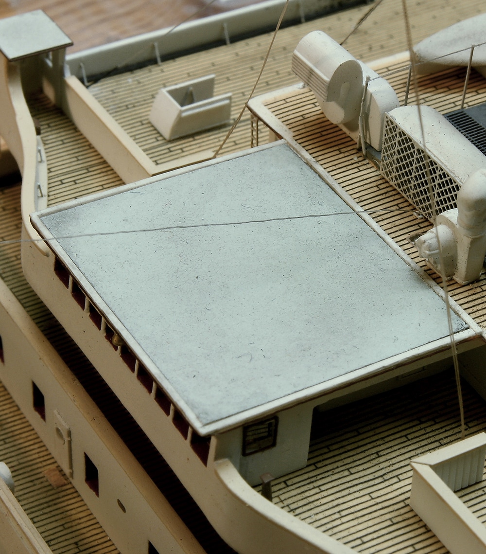
Although not visible above because of the angle of the photograph, the ventilation shaft for the Reciprocating Engine Room (beneath the unfinished skylights in the center of this photo) descends all the way through the ship. At the bottom is a section of transparent acetate printed with an overhead view of the engine. |
|
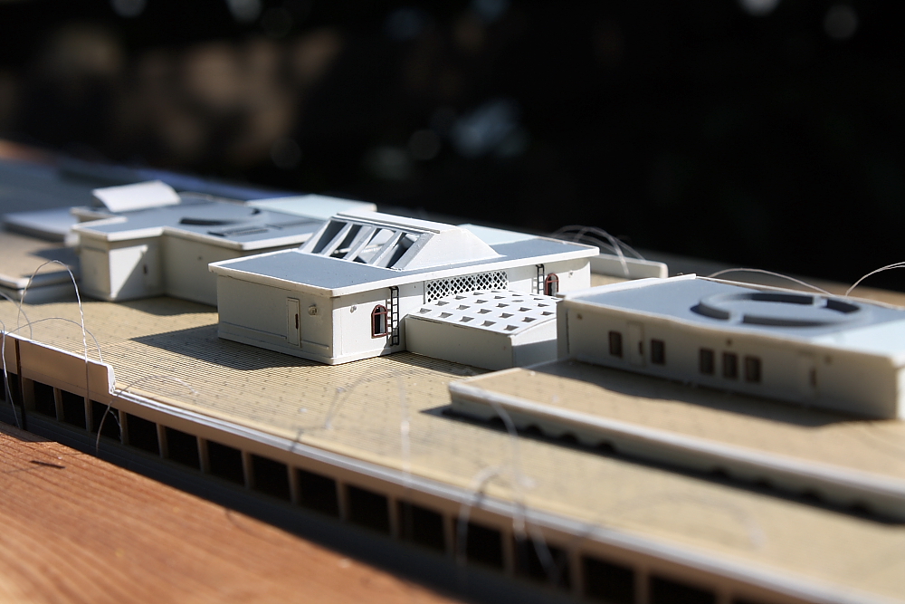
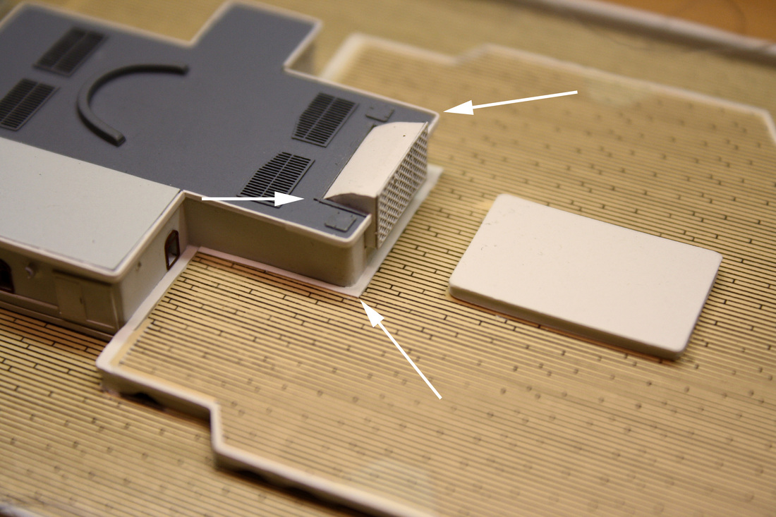
The tops of the funnel casings were given a more detailed appearance (below) by edging them with white-painted .010" x .020" styrene strips, positioned to give a slightly raised edge all around (top arrow). Narrower strips (cut down) were also used to create edging around the side and rear edges of the stokehold vents (middle arrow). Wider strips (bottom arrow) were used where the raised roofs met the deckhouses to create a clean, finished appearance and eliminate any visible joints, however slight, between the raised roofs and the deckhouses. On the real ship the deck planking would have run right up to the base of the walls, but the effect is entirely natural here. This was one of the areas where the limitations of adapting a kit model required a solution that looked natural even though the appearance differed somewhat from that of the real ship.
|
In addition, the openings for the Fidley vents on the funnel casings - seen above as four rectangular grilles on the Nos. 1 and 2 boiler casing at far right- were cut out and a void (hollow box) built underneath each. When painted flat black inside, these voids gave depth to each vent opening. The same was done to all the stokehold vents, which were scratchbuilt from thin styrene and faced with a photoetched brass grill. The photo at right also shows the tank room roof and and No. 3 funnel casing with the roof edging in place.
|
|
Below: along the base of the raised roofs and outer deck edges, the waterways were simulated by affixing narrow styrene strips painted flat black. The real waterways were depressions in the deck, but they appear the same here even though they are upraised. The black waterway strips also served to disguise the slight gaps that would have otherwise been visible between the deck and the base of the raised roof areas. At the base of the deckhouse directly opposite the skylight dome cover, the strip running along the base of the wall is clearly visible; as described above, these gave the base of the walls a cleaner finished edge.
What are described above are examples of the many "fixes" that were done to conceal minor imperfections in the kit. The same type of work was done all over the ship in subtle ways that escape notice unless you're very familiar with the kit and the ship.
Working on the model only 4 to 5 months out of the year, progress was slow but rewarding. Move the slider from right to left on the next two images to see the model as it appeared in January 2011 and January 2016. (Note: if you have a touchscreen, you'll need to move the slider with your finger - the cursor won't work with a touchscreen.)
Note: the rainbow-like lines on the "After" picture above are a phenomena of the digital camera being unable
to resolve the tightly spaced deck planking lines. When viewed with the eye the decks appear normal.
to resolve the tightly spaced deck planking lines. When viewed with the eye the decks appear normal.
|
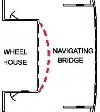
Some parts of the ship itself were rebuilt in part or completely. One example of a rebuild for historical accuracy is the Wheelhouse (right). The kit part has a curved front (dashed line in red) but Titanic's was straight. Olympic's was curved, one of many differences between the two ships that was not known when the Minicraft kit was first made. Another example is the Docking Bridge near the stern (below); that rebuild was for scale accuracy. The cast styrene parts from the kit have the right dimensions when assembled, but are too thick for the correct scale appearance. This is a limitation of any plastic model kit in scale; the parts simply can't be cast thinner than a certain size. Using sheet styrene pieces of much thinner material, it could be made true to scale. By doing the same thing all over the ship, the model began to take on the appearance of an exact scale miniature and not a model kit.
|
|

|

|
Background text and drawings from page 56 of RMS Titanic: A Modelmaker's Guide by Peter Davies-Garner. Used by permission.
Scratchbuilding structures like this isn't difficult; it just requires the right tools and bench setup. (See Benchwork.) The key to achieving accuracy in scale, and the realistic appearance that results, is to use materials of the right diameter and thickness. Sheet styrene, styrene rod and styrene strips were used extensively. When parts required stock of a smaller size than the smallest size available, it was simply trimmed down further. For example, by cutting very narrow strips from .005" sheet styrene, strips .002 x .005" were created. That's the equivalent of something 3/4" x 1-3/4" in cross section on the real ship. With a watchmaker's loupe for magnification and an X-Acto knife that's surgically sharp, there was almost no limit to the precision of the work that could be accomplished. (See Fine Details.) The following is a list of the styrene stock used most often in this build; the smallest sizes were used for scratchbuilding. (And collectively, they were the most inexpensive supplies used, given how many things were manufactured from them. Each package below supplied enough stock in its size to last the entire project.)
|
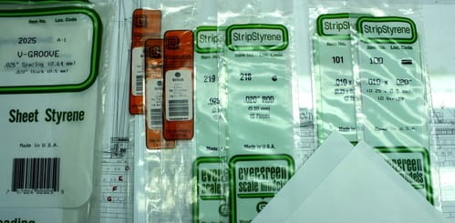
Styrene sheets: .005*, .010, .015, .040 (bulkheads) and .025
V-groove for bridge wing stairwell bulwarks) Styrene strips: .010 x .020, .015 x .030 and .015 x .040 Styrene rod: .010, .015, .020 and .025 *For many applications, strips were cut from .005" sheet styrene since the smallest pre-cut strips available commercially are the .010 x 020" size. This is too large in scale for many applications. As an example, the lifeboat gunwale strips shown on the Lifeboats and Davits page were cut from a .005" sheet.
|
|
|
MODELING RESOURCE - Click for link_____________________________________________________________________________________
|
|
Building a scale replica from a plastic model kit, even one as well-tooled as the Minicraft, does have its limitations. The hull and deck pieces, for example, need to remain a certain thickness for strength and stability and couldn't be altered. But in some places the visible edges could be eliminated: in the Well Decks, for example, the areas of the cast hull piece that formed the bulwarks were faired down to a narrow edge at the top so that the thickness of the hull piece was not readily apparent. However, it was impossible to eliminate overly thick deck and roof edges all over. Some could be concealed by making the deck-edge waterway overly wide (along the sides of the Forecastle Deck, for example). Others aren't immediately obvious but are readily visible if you know what to look for, and I don't claim to have eliminated every scale inaccuracy. It is, in the end, a ship model modified from a kit and not a replica built entirely from scratch. However, by adding as much accurately scaled detail as possible, scale inaccuracies such as deck and roof thicknesses tend to escape notice or look natural.
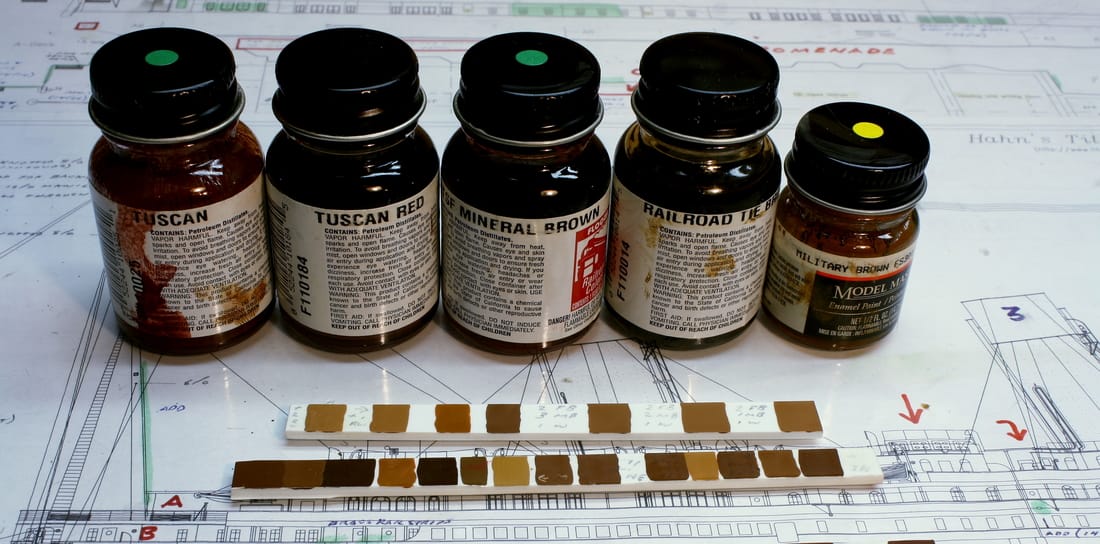
Paint colors were researched extensively, since they had to be historically accurate. Unlike colors for military models and model railroading, there are no off-the-shelf colors for ocean liners; almost all paint has to be custom-mixed for exact matches if the colors are to be historically accurate. Hundreds of mixes were experimented with - 125 for the funnel color alone, an elusive color called "White Star Buff" (see the link below, along with a link to a list of paint colors used for this model). Enamel (oil-based) paints were used exclusively, with Floquil and ModelMaster brands preferred. Testors has since discontinued the Floquil line; there's also a link below to open a PDF of equivalents in the ModelMaster line.
Note: the teak color used on the railings for my model is correct for sun-bleached teak, but I now believe it is too light. The teak color shown in the Paint Reference linked below right is the same as was used for the teak skylights on the Officers' Quarters Deckhouse. (See the end of the Lighting Systems page for a photo.)
Elevation drawing detail from Hahn Titanic Plans. Used by permission of Robert Hahn.
MODELING RESOURCES - click for links______________________________________________________________________________________
|
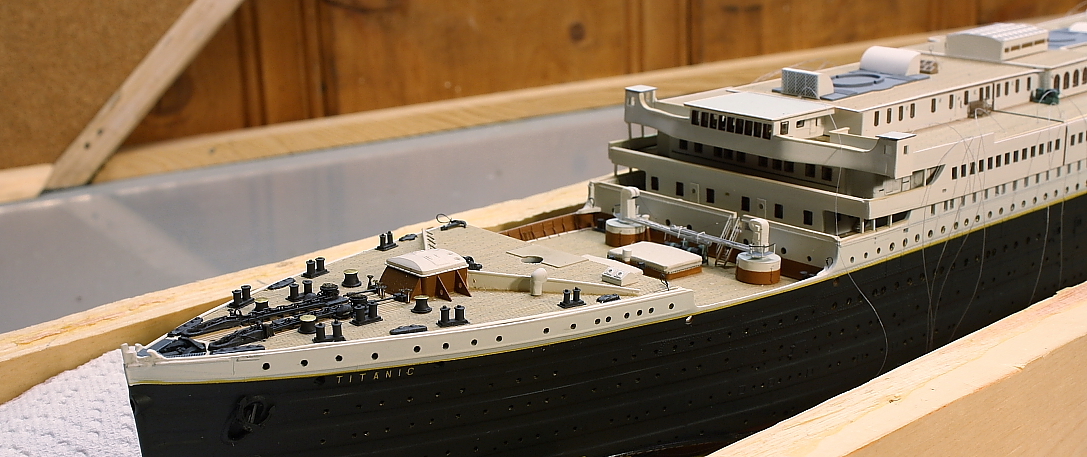
Achieving historical accuracy in the paint colors was not enough; they also had to appear realistic. If you're looking at the model from two feet away, that's the same as seeing the real ship from a distance of 700 feet. That means the colors have to look the same as if you were seeing the real ship from that distance. And at a distance, colors don't appear quite as vivid. Compensating for this in painting a model is called "scale effect". All model colors were adjusted accordingly by tinting them lighter or, in the case of the white-painted areas, adding some grey to tone down the brightness. Scale effect also means that glossy surfaces don't appear that way from a distance, and for this reason all painted surfaces were given a spray coating of flat lacquer (Testor's Dullcote) prior to installation. Scale effect, and flat paint, is why the colors in the photo below look real.
Everything that was painted, even very small parts, were airbrushed since that method of applying paint gives a uniform finish and perfect control over the amount. (It's impossible to apply too much unless you're careless or not using good judgment.) Airbrushing is also the only way to paint finer photoetched brass parts such as grilles and railings without clogging.
Primer was not used; styrene plastic doesn't require it. The hull, however, was prepped with a plastic prep solution to ensure that it was completely free of skin oil and other contaminants from the extensive handling while drilling the portholes and doing all the other detail work. Since painter's tape would have to be applied and removed in order to paint the sheer stripe and the white above it, ensuring good paint adhesion was critical. After painting, white cotton gloves were worn anytime it was handled. This prevented fingerprints that would have readily been visible on the flat black surface.
Primer was not used; styrene plastic doesn't require it. The hull, however, was prepped with a plastic prep solution to ensure that it was completely free of skin oil and other contaminants from the extensive handling while drilling the portholes and doing all the other detail work. Since painter's tape would have to be applied and removed in order to paint the sheer stripe and the white above it, ensuring good paint adhesion was critical. After painting, white cotton gloves were worn anytime it was handled. This prevented fingerprints that would have readily been visible on the flat black surface.
Extra gray was added to the white paint used on the ventilators, lifeboat davits and davit blocks. Although the same white paint was used everywhere on the real Titanic, the added grey here ensured that those fittings didn't look overly bright in scale. Small white-painted objects that stand up and out from other details tend to reflect light more than flat surfaces.
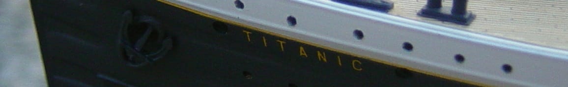
The sheer line - the yellow-gold stripe between the black and white areas of the hull - was airbrushed on after carefully masking the line with Scotch #471 blue plastic tape in 1/8" width. After working the tape carefully between the rivet lines, a second line of tape over the first one held sheets of newspaper to cover the rest of the hull. As with every color on the ship, countless paint mixes were experimented with before a satisfactory match was found for the color Harland & Wolff called 'yellow chromate'.
|
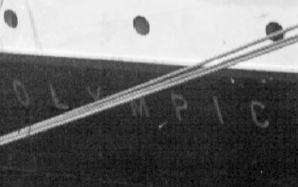
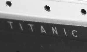
The "TITANIC" letters on each bow have been subject to controversy over the years, with researchers unable to agree whether or not the letters were perfectly vertical or angled forward. Those who hold to the belief that they were straight up and down believe that the appearance of angled letters in the Olympic photograph at left is due to the flare of the bow. Since I believe they were vertical, I could not use the decal letters from the kit which are angled. Instead, extra decal sets were purchased from Minicraft and the letters from the stern (which are vertical) were cut out individually and applied to the bow.
At left, photos of the name on the starboard bow of Olympic and this model, taken from the same angle. Below, the view of the same lettering from abeam. 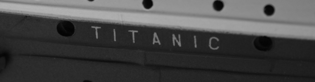
|
|
Weathering was an important consideration. By the time Titanic sailed on her maiden voyage, she was not a new ship. She had been subject to the damp Belfast climate as well as smoke from her funnels and soot from coaling. Although her decks were washed in preparation for departure from Southampton, a great deal of soot remained on her funnel casings and deckhouse roofs. Photos also show that the corners and edges of some of her upper decks were dirtier than other areas.
To replicate the soot residue on the areas that would not have been cleaned prior to Titanic's departure from Southampton (mainly on the tops of the Boat Deck roofs and funnel casings, and the ventilators in those areas) AIM Weathering Powder in Soot Black was used. Applying a very slight amount with a soft dry paintbrush, then spreading it around with a paintbrush soaked with water achieved the exact look of soot residue after many rains. The effect is subtle and difficult to see in photographs, but is very realistic when seen with the naked eye. For the funnel tops, weathering powder was applied directly to replicate the heavy coal smoke residue in those areas. For the corners and other out-of-the way areas of the outer decks that required a bit of dirtying, the same technique was used as with the funnel casings. Weathering powder was brushed directly on the canvas hatch covers and lifeboat covers.
|
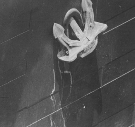
Simulated areas of dirt and grease were also added to the Forecastle and Well Decks, and rust was also added to some of the shell plate joints on the white-painted area of the hull on the starboard side*, and to the starboard anchor chain. The rust was simulated by drybrushing the appropriate colors. The vertical scrapes on the hull below the starboard bower anchor** was drybrushed with primer grey.
* Prior to sailing day at Southampton, crewmen touched up the white paint on the port side of the ship facing the dock, but not the starboard side.
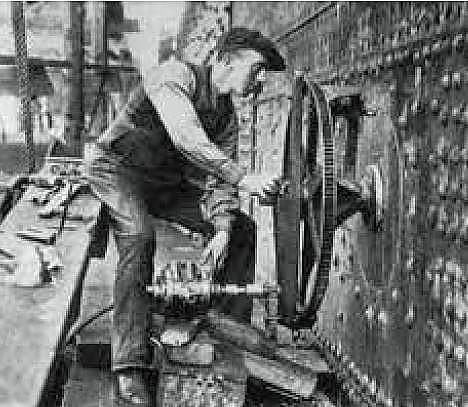
** While leaving Southampton, the suction effect caused by Titanic passing close to the New York caused the latter ship to part her mooring cables. Titanic's Captain Smith ordered the starboard anchor lowered to the waterline in case it had to be deployed quickly to arrest her forward progress, and the flukes of the anchor scraped the paint between the water and the anchor hawse. See the thumbnail photo below for similar scrapes on Olympic's hull.
* Prior to sailing day at Southampton, crewmen touched up the white paint on the port side of the ship facing the dock, but not the starboard side.
** While leaving Southampton, the suction effect caused by Titanic passing close to the New York caused the latter ship to part her mooring cables. Titanic's Captain Smith ordered the starboard anchor lowered to the waterline in case it had to be deployed quickly to arrest her forward progress, and the flukes of the anchor scraped the paint between the water and the anchor hawse. See the thumbnail photo below for similar scrapes on Olympic's hull.
|
MODELING RESOURCES - Paint colors used for drybrushing______________________________________________________________
RUST ON ANCHOR CHAINS: Testors 1185 Rust
ANCHOR SCRAPES ON HULL - Floquil 110009 Primer
RUST ON SHELL PLATING JOINTS ON WHITE-PAINTED STRAKES - Testors 1166 Flat Brown
|
|