|
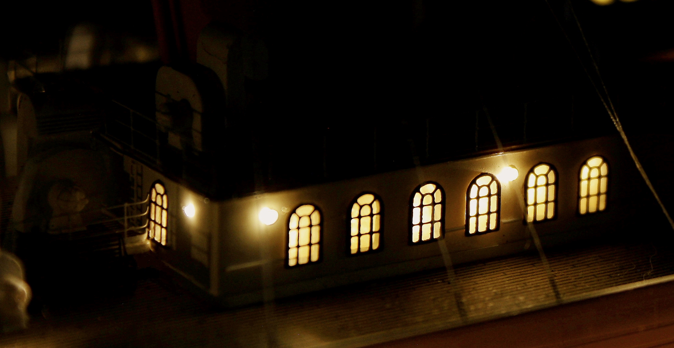
I decided early on to model Titanic as she appeared at anchor off Cherbourg just after sunset on April 10, 1912, precisely as artist Ken Marschall depicted her in his iconic painting "Au Revoir to the Old World" - right down to the exact staterooms he depicted with the lights on. The goal was to accurately replicate the lighting in scale, so that the illuminated model would look exactly like the real ship in miniature and not simply a model with lights inside. |
|
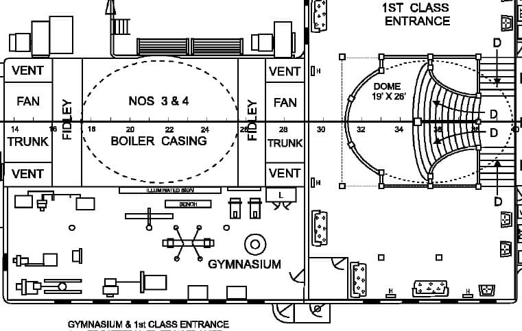
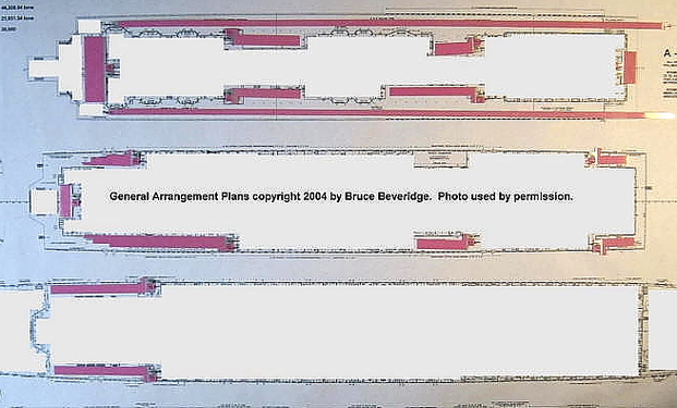
Detail of General Arrangement Plans by Bruce Beveridge used by permission. |
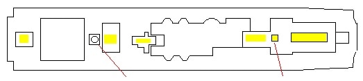
Above: the 1st Class Gymnasium on the Boat Deck as shown on the plan below.
As with the exterior details, careful planning had to go into the lighting. In order to be accurate, the correct windows and sidelight had to be illuminated. It would not do to have light coming from storerooms or machinery rooms that wouldn't normally be occupied. For this purpose I used Bruce Beveridge's General Arrangement plans (detail at left) as they identify every room and compartment within the ship as to its purpose. For a look at the artwork that this model's lighting was based on, click below. |
Modeler note: if you're thinking about illuminating your model, you should be aware of the following:
|
|
- It takes a significant amount of planning to do it successfully. The modeler has to be able to think far ahead at all times.
- Adding one or more lighting components to a model can increase the cost significantly. Expect to spend a minimum of $125 for the interior lighting alone before any color corrections are made. - Some basic knowledge of wiring and electronics is required to avoid inadvertent damage to expensive components and injury from electrical shock. Nothing on this page is intended to be used as step-by-step instructions for any lighting shown. |
|
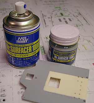
The challenges of lighting a plastic model were complicated by the fact that styrene plastic, except when cast in black, is transluscent - you can see light through it. A way had to be found to lightproof all interior surfaces, including the undersides of the decks, so that the plastic wouldn’t glow from the light within. Various materials were experimented with until a liquid material called Mr. Surfacer was found to do the job perfectly. This is the grey color seen on the undersides of the deck and roof pieces in many of the photos in this page. Normally used as a filler for small cracks and surface imperfections, Mr. Surfacer contains talc which acts as a light blocker when properly applied. A thick coating of this material was applied to the interiors of all walls, ceilings and deck pieces, and where possible applied to the inside joints where two pieces met. (The insides of the walls were painted white afterward.) Before installation all treated pieces were checked for light blockage by holding them up against a bright light.
Deck plan detail in background from Hahn Titanic Plans. Used by permission of Robert Hahn. |
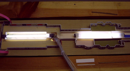
The interior lighting was the first consideration. This was the light that would show through the windows, sidelights (portholes) and skylights. The clear choice was miniature cold-cathode fluorescent lights (CCFLs). These have the advantage of producing a soft, uniform light in all directions without glare while generating almost no heat in the process. Their life expectancy is around 15,000 hours, which would be of critical importance since the lights would be sealed inside the decks once the model was complete. One 4" and two 8" lights were used in the hull and three 4" lights were mounted within the superstructure. The interior deck pieces were cut out at strategic locations to allow light to penetrate throughout the superstructure and up into the deckhouses of the Boat Deck.
|
|
MODELING RESOURCES - click for links______________________________________________________________________________________
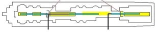
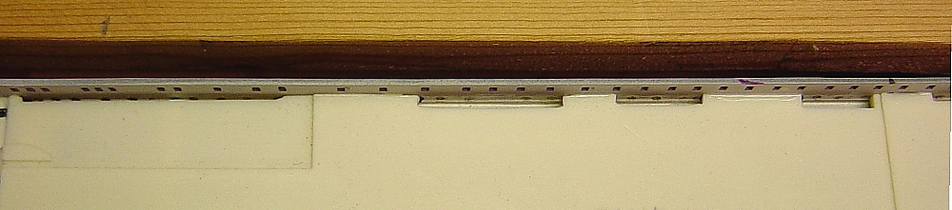
Below, an overhead view of the B/C deck piece where it meets the inside of the hull. Since the edge of this is in line with the C-Deck sidelights (portholes), this piece had to be notched in order to allow light to illuminate some of them. As not all staterooms would have been occupied, not all sidelights had to be exposed.
|
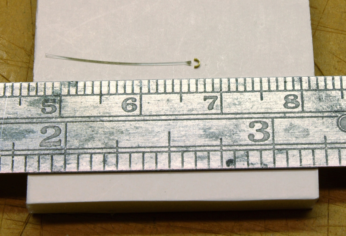
To replicate the exterior decklamps, .25mm fiber optic lighting was employed. The light source consisted of a simple pre-wired LED positioned against the end of the fiber optic bundle and sealed inside a length of heat-shrink tubing. The bundle led upward through the ship with strands branching off at various points up and into the various deckhouses and other places where decklamps were mounted. At each decklamp location, a fiber optic strand was led through the bulkhead (wall) extending a few fractions of a millimeter out the other side. The tiny point of light that would emit from the end of each strand would simulate the light from the decklamps and actually provide illumination for the decks at night.
|
|
MODELING RESOURCES - click for links______________________________________________________________________________________
|
|
|
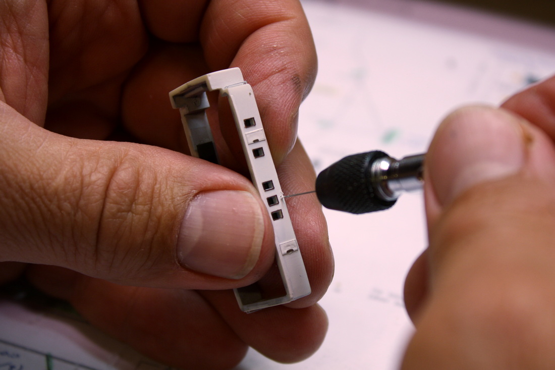
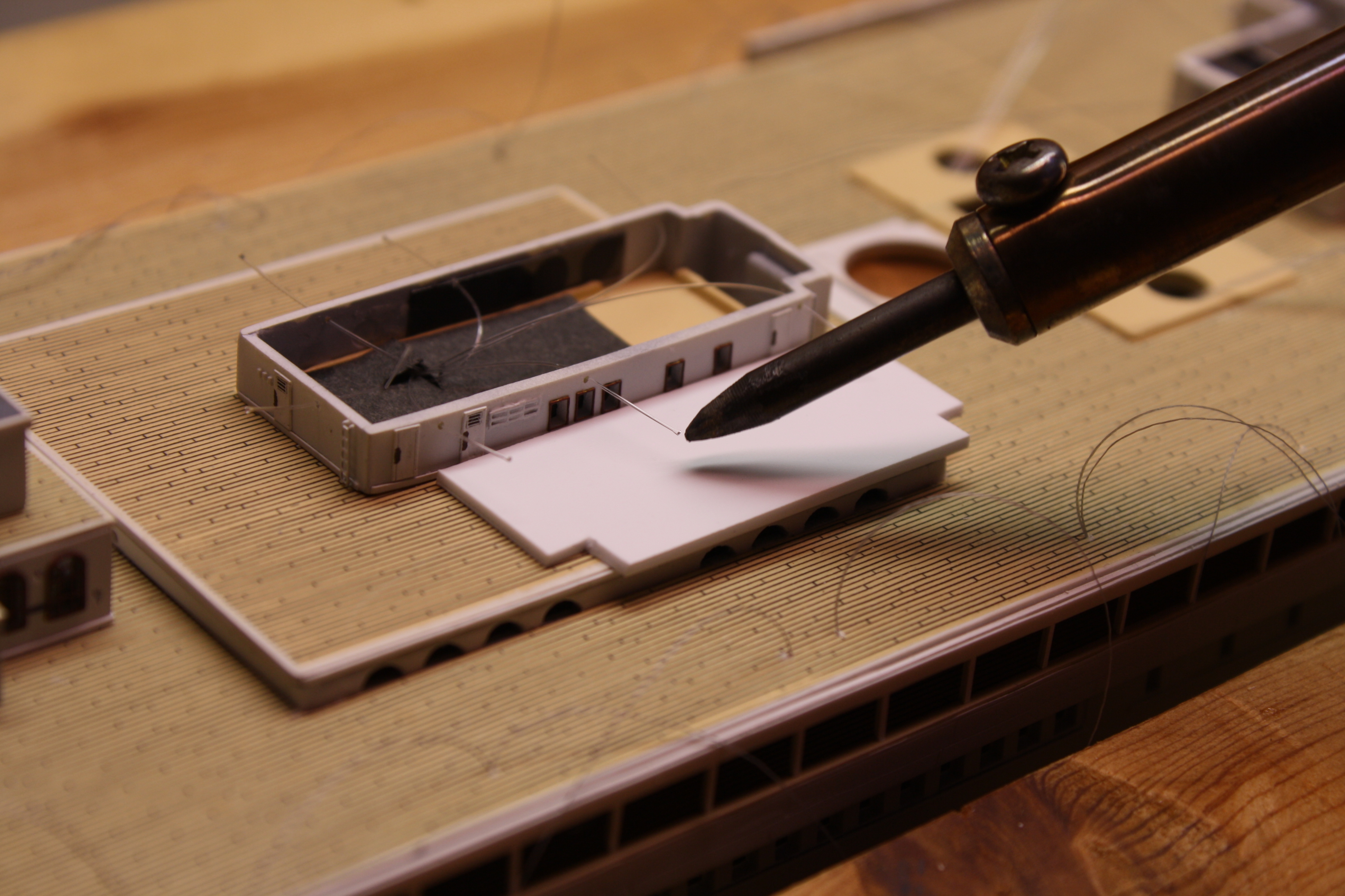
After drilling each fiber optic strand through the bulkhead, it was flared and rounded slightly at the tip by briefly holding the tip of a hot soldering iron near it. (When doing this, the deck was protected against heat by a thick piece of styrene plastic.) Each strand was then pulled back snugly against the bulkhead and secured with Elmer's Glue. (CA cement was not used because it makes fiber optic strands brittle to the point where they can snap off easily). The purpose of flaring the fiber optic tips was partly to create a rounded lens at the end, but also to prevent the strand from pulling back through the bulkhead.
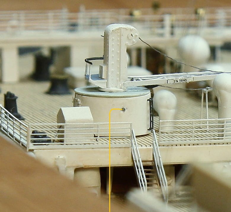
The fiber optic strands for the cranes on the Poop Deck (right) presented a problem because the space beneath them is completely exposed, and fiber optic strands can't be bent 90 degrees. To get a fiber optic strand up into each crane base, they were run from beneath the well deck and through the supporting crane post underneath after drilling a .25mm shaft through it. |
|

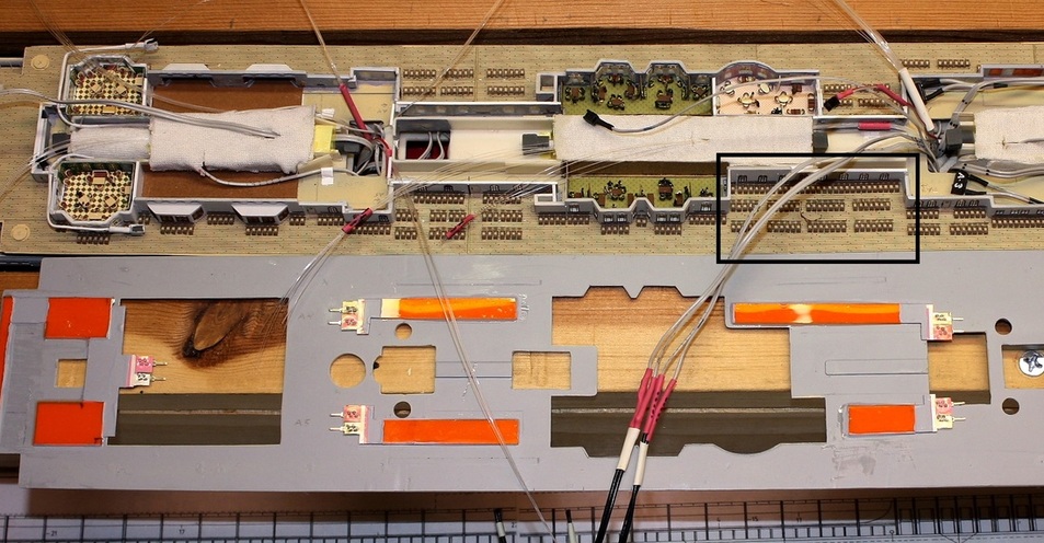
The image above shows the profusion of fiber optic strands leading up into the various deckhouses. Decklamps were also mounted on crane bases, stokehold ventilators and railings. There are 61 outward-facing deck lamps replicated with fiber optics. Extra strands were run as insurance in case of damage.
|
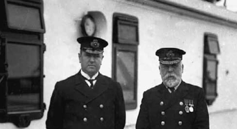
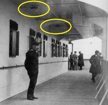
On the Boat Deck, the lamps along the forward half of the deck had shields around their forward halves. (One is visible directly behind Purser Herbert McElroy in the image to the right). Shielding the lamps in this manner was done so they could not be seen from the Navigating Bridge in order to preserve the officers' night vision. To replicate these shields, small strips of brass were cut and bent to a half-circle, then dipped in white paint and cemented around the holes drilled for the decklamps. |
|
|
|
The funnels were not illuminated in any way. In the film "TITANIC", director James Cameron did so for cinematic effect only.
|
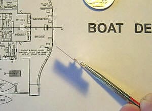
With CCFLs illuminating the interior of the ship and fiber optics replicating the deck lamps, a solution still had to be found to replicate the overhead-mounted lamps on the outer decks. These provided light to the covered areas of the Promenade Deck and the deck overhangs fore and aft – the forward B Deck area beneath the Navigating Bridge, for example (right). With open deck space above and below, nothing could be run from the deck above without being readily seen. Fiber optic strands are low-profile and could have easily been run beneath the deck surfaces from inside, but they lose their ability to radiate light from the tips when bent 90 degrees downward. Several other options were considered and discarded as unworkable before finding electroluminescent film. It would be an ideal solution: it’s paper-thin and can be cut to any shape, but when energized with an electrical current it fluoresces with a blue-white light. Because it’s virtually invisible from the side, it could be laminated to the underside of the deck pieces to radiate light downward.
|
|
|
|
Background plan details from Bruce Beveridge's General Arrangement plans. Used by permission.
|
|
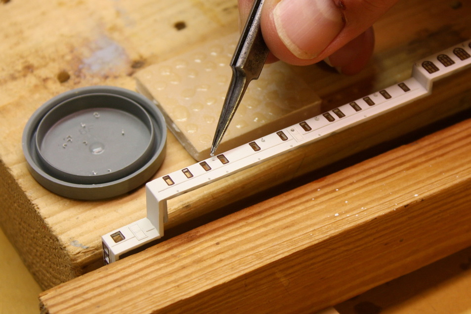
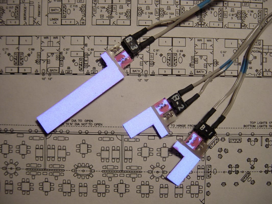
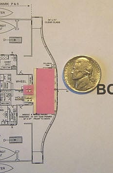
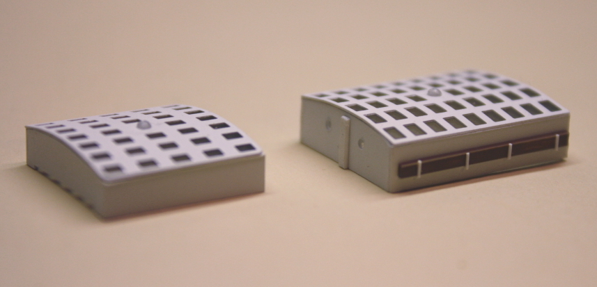
Some of the E/L strips were very long, such as the ones that ran the full length of the Promenade Deck. Others, such as the ones needed for the deck overhangs fore and aft and the Promenade Deck bays, were much shorter - some replicating only two or three lamps (above right). The plugs to the two electricl contacts on each strip were concealed inside the superstructure, with the E/L film extending over the tops of the bulkheads. The image at right shows all the E/L film pieces laid out on a set of deck plans in the locations where they would be installed. From top to bottom: the Promenade Deck, B Deck and C Deck. Not shown are the strips that would be mounted beneath the overhang of the Poop Deck to illuminate the after 3rd Class entrances off the Well Deck. |
|
In order to locate the plugs inside the ship, the tops of the bulkheads at each of these locations was notched just enough to accommodate the thickness of the E/L strip. Each strip - connected to its associated plug just inside - would extend over the top of the wall and would be positioned directly over the area that it would illuminate. An application of Mr. Surfacer would coat any area of a particular strip that did not need to radiate light - the part that ran over the top of the walls, for example.
|
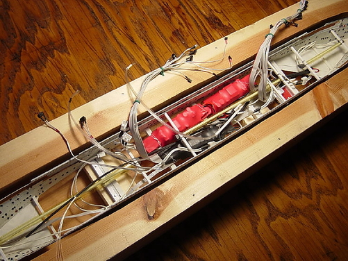
From an engineering standpoint, being a waterline model complicated things. Three independent lighting systems would mean a lot of wiring, and the cut-down hull would have to contain all the fiber optic strands and in addition, the bulky CCFL inverters. (The inverters are visible at right; two are red and one is black.) This requirement reinforced the decision to use the light sources chosen, since all would be sealed inside the hull and not replaceable once the first deck piece was in place. CCFLs, as noted, have an estimated life of over 15,000 hours and the LED illuminating the fiber optic strands 50,000. At the same time, getting the necessary wires and fiber optic strands to the various decks and deckhouse had to be carefully planned, since there would be no way to reroute or add something missing once the hull was sealed. |
|
|
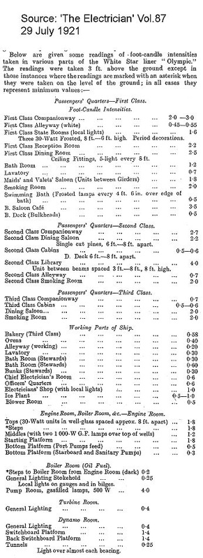
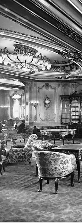
While the question of how to light the model was solved, there were still several problems to overcome. The first was the lighting levels. James Cameron's film "Titanic" portrayed the ship brilliantly illuminated inside and out. In reality the lighting levels in 1912 were much lower. Outside, the 1st and 2nd Class decks would have been bathed in a warm, yellow glow, barely a fraction as bright as the floodlit decks of today's cruise ships. The deck lamps would have provided enough light to see, but not beyond 200 feet or so. Inside, nearly all of Titanic's interiors would seem very under-illuminated by today's standards. The brightest bulb on the real ship was the equivalent of a 75-watt bulb of today, and the equivalent of 25 and even 15 watts was common in many areas (1st Class Staterooms had only three 30-watt bulbs). One example is the 1st Class Reception Room, with a light level of 2.2 foot-candle intensities measured at a height of 3 ft from the ground. (See table at right, courtesy of Scott Andrews.) Compare this to a large hotel lobby of today, where the standard is 10 foot-candles. Another example is the 2nd Class Library, measured at 4.0 foot-candles. The standard for a library reading room today is 30. For this model, the light provided by the CCFLs would have to be reduced quite a bit to achieve historically correct light levels.
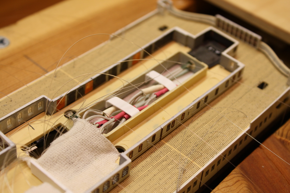
After initial experimentation, it was found that wrapping the CCFLs in a layer of ivory-colored cotton (lightweight t-shirt material) would both reduce the amount of light and diffuse it further. Since CCFLs emit almost no heat and would only be on for brief periods of time when the model was shown, it was an ideal solution.
Below: the 8" tube in the forward area of the hull (inside the cloth) 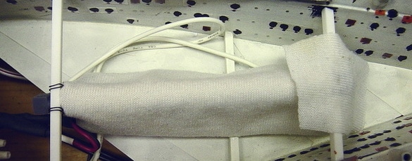
|
|
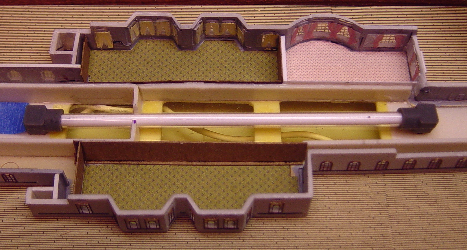
In some areas the light level was reduced even more by cementing additional layers of styrene or construction paper in strategic locations. The goal was for the light to be uniform within each type of room, and the light levels accurate for the type of room. The 1st Class Smoking Room, for example, would have been much more dimly lit than the 1st Class Reading and Writing Room. Although CCFLs aren't overly bright to start with, their light would be confined to a relatively small space and had to be cut down.
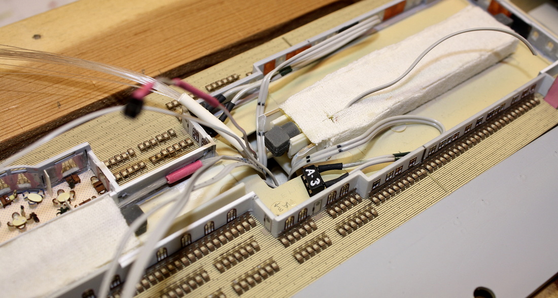
In the image above, cotton fabric covers not only the space above the lights, but is also cemented to the inner styrene "walls" on either side of the lamps. This had to be done to diffuse and reduce the light further because of the windows opposite. This photo also shows how the Grand Staircase opening was used as a cableway for the fiber optics and electrical wires. In the foreground, the plug for the E/L film strip marked 'A-3' is in place and ready to be connected to the lightsheet on the inverted deck piece as it's put into place. That particular strip would extend over the bulkead to the left of the connector through the slim notch and illuminate the Promenade Deck bay in the left foreground.
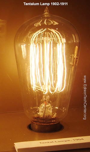
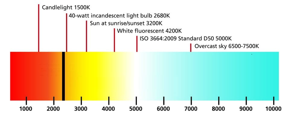
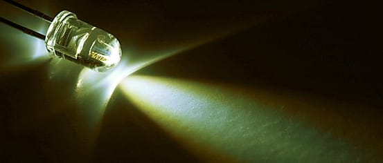
Another problem was the color of the light sources used for the model. The CCFLs produce a slightly blue-white light with a color temperature around 5,000K (Kelvin), the color of daylight. The E/L film produces a very blue-white light with a color temperature of about 6,500K. In contrast, a modern 40W incandescent light bulb is less than 2,700K. Titanic's tantalum-filament bulbs, similar to the one below, would have had an even lower color temperature - probably around 2,300K. Seen from a distance in 1912, the light emanating from Titanic’s portholes and deckhouse windows would have had a noticeable amber-yellow hue to it. All the lighting would have to be corrected to this range.
|
|
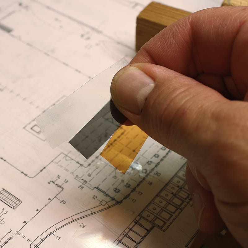
Fortunately, the interior lighting was a relatively easy fix and could be corrected through the use of "gel sheets": transparent and semi-transparent material that comes in hundreds of different color temperatures. These are the heat-resistant filters that are placed in front of theater spotlights to create various lighting effects on stage.
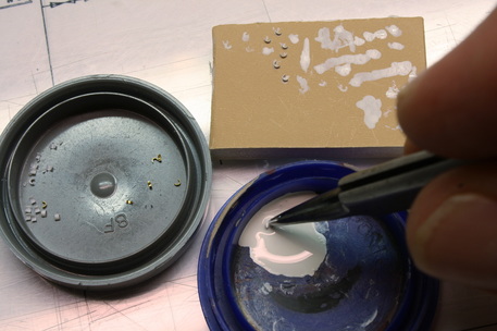
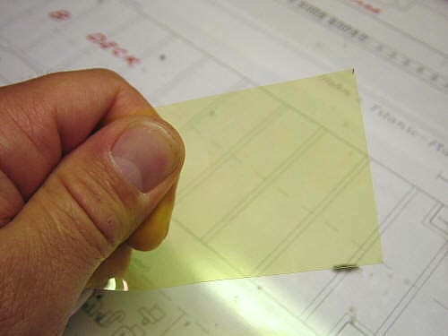
Experimenting with various colors determined that a filter of a pale yellow color (below left), when wrapped around the CCFLs, altered the color temperature of those lights to the desired value. (This was a visual assessment, not measured with a color temperature meter). The wavelength of the E/L film was corrected by overlaying filter material of a darker orange color. Because the E/L film produces a light with a much higher color temperature, more correction was required.
Experimenting with various colors determined that a filter of a pale yellow color (below left), when wrapped around the CCFLs, altered the color temperature of those lights to the desired value. (This was a visual assessment, not measured with a color temperature meter). The wavelength of the E/L film was corrected by overlaying filter material of a darker orange color. Because the E/L film produces a light with a much higher color temperature, more correction was required.
|
The E/L film pieces themselves were laminated to the underside of the deck pieces and overhangs with an epoxy resin compound that dries clear, then pieces of filter material cut to the same size were laminated on top of them. The filter material used over the E/L film has a lower transparency (light transmission factor) which serves to reduce those light levels further.
MODELING RESOURCES - Roscolux filters used ______________
|
|
The LED used to illuminate the bundle of fiber optic strands was a "warm white" type, rated about 2,700K. To correct the color a bit more, two small discs of gel filter material were inserted between the LED and the fiber optic bundle. No reduction in brightness was required since this LED was much less bright than the typical "bright white" or "ultra bright" LEDs.
|
|
The image below shows the temperature-corrected E/L film in place on the underside of the deck piece that covered the Promenade Deck. This deck piece, positioned upside down, is ready for installation. The entire underside has been coated with Mr Surfacer . The E/L strips extend over the top of the bulkheads through notches barely deeper than the thickness of an index card. They have gel filter material laminated on top of them, and the areas of the E/L strips that did not need to radiate light have been painted with Mr Surfacer. Although the gel material laminated the E/L strips appears deep orange here, they correct the color to a warm yellow glow - exactly as required to simulate 1912 lighting.
This image also shows the complexity of lighting this model. The E/L film pieces had to be positioned so that their terminals would remain inside the ship, and the notches in the bulkheads precisely located to accommodate them. Since the interior of the ship couldn't be accessed with the upper deck piece in place, the terminals would have to be connected before the deck piece was put in place. Everything had to be right the first time because once cemented in place, none of it could ever be accessed again. On top of that, the wiring and plugs had to fit within the small space available could not block any of the light from the CCFLs from reaching the windows. Fitting this profusion of wiring and fiber optics inside the very narrow deck height was extremely difficult, but when it was finished there was nothing visible to suggest that any of it existed at all.
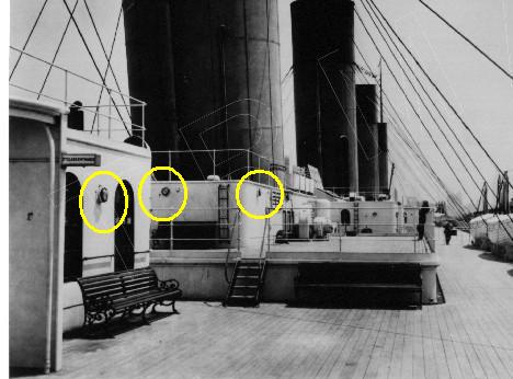
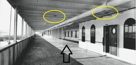
Below left, Olympic's Promenade Deck is shown with two of the overhead deck lamps circled in yellow. On the photo above this bay is indicated by a black rectangle. Below right is the same bay on the model. With the corrections in place for color temperature and brightness, the model's lighting systems perfectly replicate 1912-era incandescent light.
|
|
Color temperature is also an important consideration when using an artificial light source to illuminate the model.
Although the finished model is displayed in a room with windows on two sides that allow indirect natural light to illuminate
the model, the model won't always be seen in daylight. When an indoor light source is needed, a portable LED desk lamp with
a swing arm is used; I specifically chose a model with adjustable color temperature. By using a setting of 6500K (the
same as sunlight) the colors on the model would appear exactly the same as they would outside.
So that the windows and sidelights would reflect the outside light and give the appearance of glass, clear acetate was applied in long strips inside the openings. Staying true to Ken Marschall's painting, some of the windows and portholes would need to have an orange cast to them to simulate drawn curtains. For these staterooms, squares of filter material of an orange color were cemented on top of the acetate strips. These also served to dim the light coming from these rooms because of the further reduction in light transmission. A further refinement to all portholes, and all windows without visible interiors, was to use strips of filter material that was slightly opaque on one side instead of clear acetate. This would blur the view through it, but the side facing out would be shiny like glass.
|
MODELING RESOURCES - Roscolux filters used____________
|

|
|
|
Above left, the filter material used inside stateroom windows and sidelights (portholes). From left to right: #119, #98 and #18. Above right, pieces of this filter applied over the interiors of the window openings. The dark grey filter material was used over staterooms that were dark inside, and then painted black inside to block all remaining light. (After experimentation it was found that clear acetate painted black on the inside looked black on the outside in the daytime, whereas sidelights and windows with grey filter material painted black gave a neutral appearance and could not be distinguished from the others.)
Left image: background plan detail from page 94 of RMS Titanic: A Modelmaker's Guide by Peter Davies-Garner. Used by permission.
Left image: background plan detail from page 94 of RMS Titanic: A Modelmaker's Guide by Peter Davies-Garner. Used by permission.
A major challenge was making the entire ship "light tight", or preventing light from escaping from the joints where the bulkheads (walls) met the deck pieces. Even the most well-made styrene model kit isn’t intended to fit together so perfectly that no light will escape. Yet even one sliver of light where it didn’t belong would destroy the illusion of a ship in miniature and show it to be what it really is, a model. Walls were not a problem where they joined at the corners, nor where they met the deck. But where roofs and large deck pieces sat on top of the walls, light leakage resulted from imperfections that could only be partially overcome by corrective work. The solution was to use small strips of black construction paper along the top corners of some walls; the strips extended overlapped the joint and blocked any remaining "leakage" when the upper piece was in place.

The location of the these black paper flaps had to be determined by trial and error by pressing the deck (roof) piece tightly down against the bulkheads and looking to see if any light escaped. Where it did, another black paper strip was added. Also note the ivory-colored paper cemented to the underside of the deck piece - this would soften the reflected light from the ceiling.
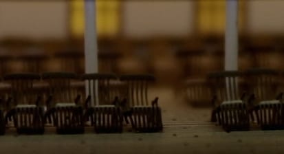
(Unrelated to lighting, to the left of the stokehold vent in the photo above, can be seen one of the voids positioned below two of the Fidley grates forward of the No. 2 funnel. This depth behind the grates gave the illusion of an actual shaft space.)
(Unrelated to lighting, to the left of the stokehold vent in the photo above, can be seen one of the voids positioned below two of the Fidley grates forward of the No. 2 funnel. This depth behind the grates gave the illusion of an actual shaft space.)
|
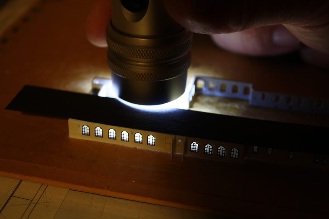
Another common source of light leakage was around the edge of the photoetched brass windows. Since the P/E window frames barely overlapped the edges of the openings, pinpricks of light frequently showed beneath the edges. To ensure that all the windows would be light-tight, each frame was sealed against the wall from the inside by running a light bead of Krystal Klear. The bead of Krystal Klear was then painted with Mr Surfacer to block any light from escaping.
Repeated checks for "light tightness" around the P/E window frames were made by illuminating the various rooms inside the completed windows with a very bright LED light, and touching up any gaps with another bead of Mr Surfacer. |
|
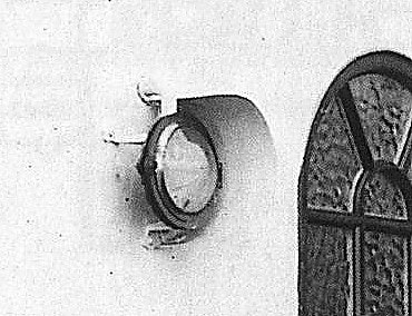
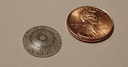
The skylights over the two 1st Class grand staircases, while not actually part of the lighting system, are shown here since they're visible at night when illuminated from within. For this reason they had to be modeled in a manner that would accurately replicate the delicate pattern of the wrought-iron framework. The original kit part was a thick piece of clear plastic with the framework pattern crudely cast into the surface and could not be modified to the level required. Up to this point no satisfactory solution had yet been devised by the Titanic modeling community to accurately replicate these domes. I hit upon the solution of using glass wristwatch crystals for the domes themselves, and then applying decals of the iron framework pattern made from the detail drawings on the Hahn Titanic Plans. The decals were created by printing the patterns of the framework onto blank decal paper, and then applying the decals to the curved surfaces with a liberal amount of Micro-Sol and Micro-Set (these help soften, conform and bond flat decal material to uneven surfaces). The result were completely "lifelike" domes that fully duplicated the complex pattern of the framework in the correct shapes.*
*The forward skylight on the real Titanic was not quite as elongated as the one made for this model, but since the actual outlines of the dome is difficult to see through the dulled glass of the cover the difference would not be readily apparent.
*The forward skylight on the real Titanic was not quite as elongated as the one made for this model, but since the actual outlines of the dome is difficult to see through the dulled glass of the cover the difference would not be readily apparent.
|
|
|
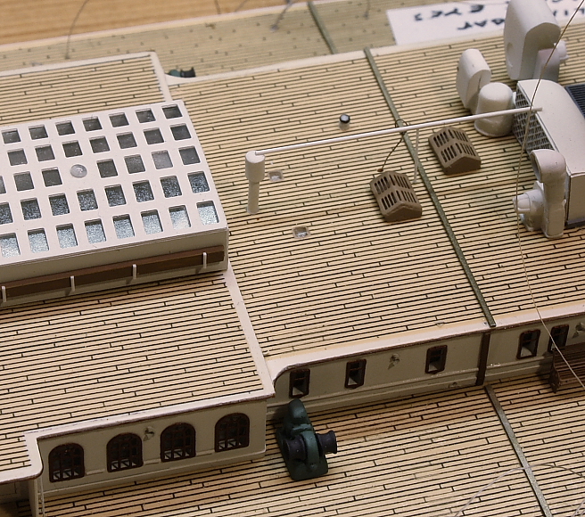
To the right of the skylight in the images below are two square prismatic skylights set flush with the deck; these transmitted light to the elevator machinery room below. To the right of those are two teakwood skylights over the Marconi Operating Room and the Officer's lavatory. At night, all of these skylights show light from within as seen below.

|
|
The dulled glass in the skylight dome covers was simulated with the same lighting filter material used for the pebbled glass windows in the 1st Class Gymnasium windows, as the appearance is nearly the same. Its appearance is readily visible above.
MODELING RESOURCES - click for links______________________________________________________________________________________
|
|