|
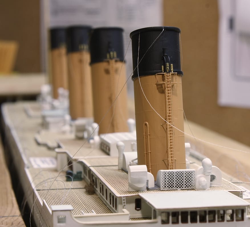
Of all the structures and fittings on the ship, the funnels are what draw the eye and stand out - literally and visually - from everything else. They're also the highest point of the ship, and anyone viewing the model would be looking around and past them to see everything else (at least on the Boat Deck). For this reason their detailing had to equal or exceed every other area of the model.
The most time-consuming work was the funnel piping. Although the steam and water pipes supplied with the kit are well detailed, manufacturing limitations prevent them from being cast finely enough to be scale accurate and their configurations were historically incorrect in certain regards (although in ways that only a true "rivet counter" could identify). If they could successfully be replicated in scale, it would be one of the most impressive modifications of the build. |
|
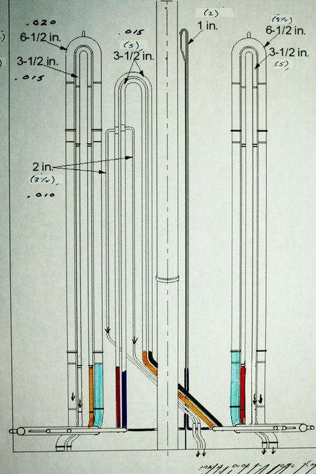
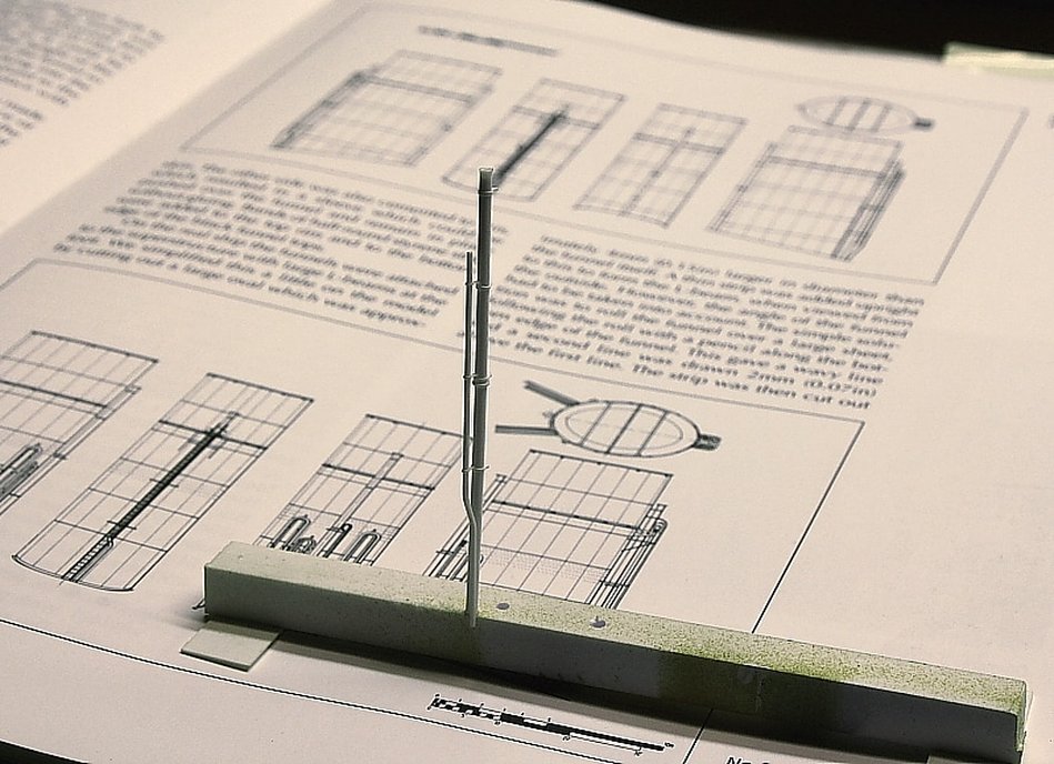
After cutting off the pipes cast into the funnels and sanding those areas smooth, the replacement pipes were made from styrene rod. The smallest rod used was .010 inches in diameter; this was used to replicate the 3-1/4" diameter pipes shown on the drawing at right. (The sizes printed on the plan in inches are the smaller bore sizes, or interior diameters). To put the scale sizes in perspective, it would require 100 rods .010" in diameter to fill one inch if laid side by side.
All the pipes had to be curved at the top with the application of just enough heat to bend the pipes without melting them. The complex bends and overlaps at the base of the funnels also had to be carefully replicated so that all the pipes would branch off at the right points and in the right direction. (Thanks to Bob Read for providing this diagram with diameters, and to Bill West for providing period specs for iron piping) |
|
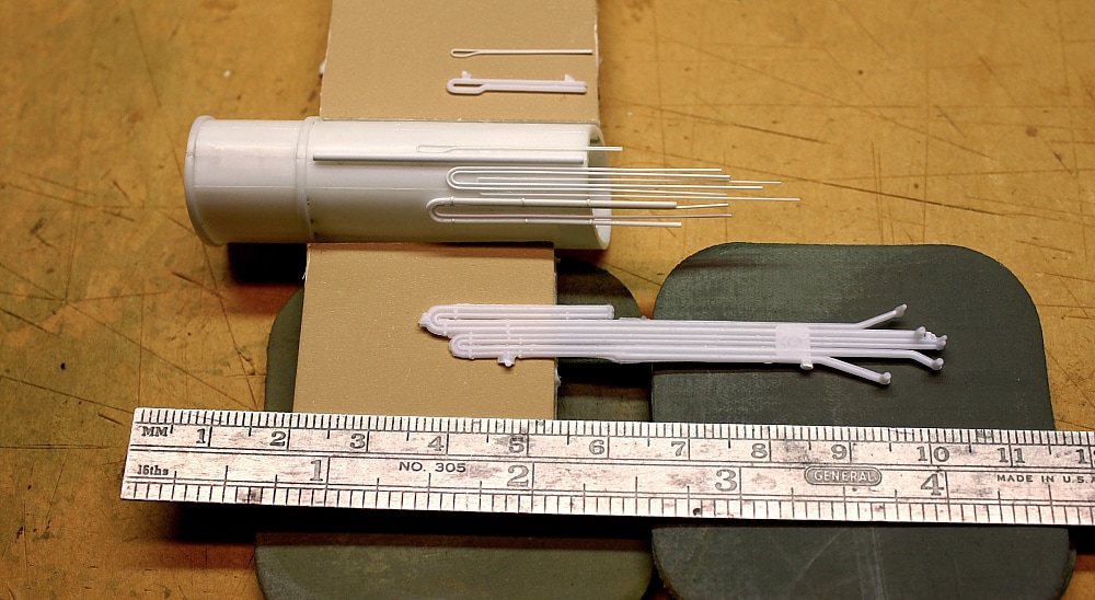
In the photo above, the difference in detail between the scratchbuilt pipes and the cast styrene ones can readily be appreciated. The same comparison can be made with the smaller P-shaped pipes positioned on the far side of the funnel.
|
|
|
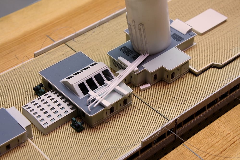
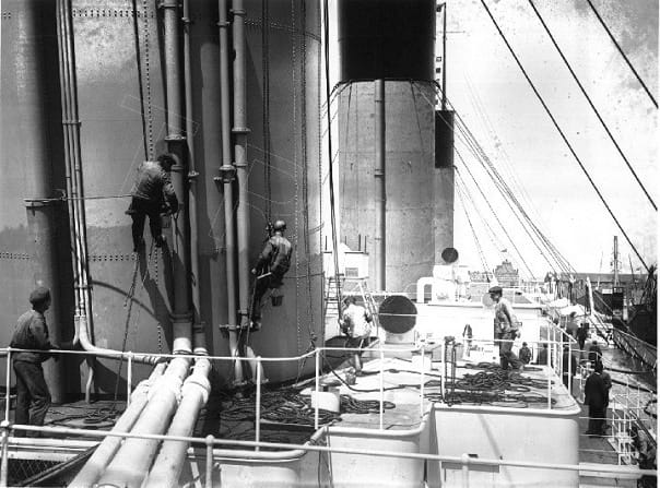
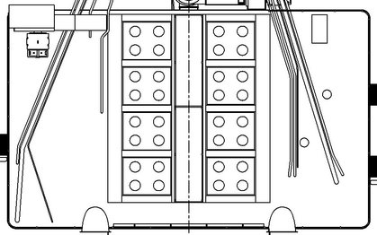
Before the funnels were painted, the pipes running laterally to the Tank Room roof had to be cut and bent. Multiple pipes of different sizes with individual bends had to mate to their corresponding pipes on the funnel in what had to appear as seamless connections. In addition the pipes had to run through the railings on the edge of the roof, under an adjacent roof-top ventilator to be added later, and elevated just above the roof surface. The pipes leading to the base of the funnel would have to be larger in diameter than the pipes running up the side of the funnel; this is because of the lagging (insulation) that was on the lateral pipes of the real ship (Olympic's shown above right). Drawing courtesy of Bob Read
|
|
Background image and text from page 125 of RMS Titanic: A Modelmaker's Guide by Peter Davies-Garner. Used by permission.
|
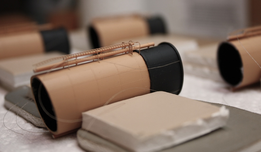
The boiler steam escape pipes, shown above, were the most difficult to engineer because they were not mounted flush against the funnels - they had brackets that held them out away from the funnels. Attached to them, also with standoffs, were the smaller steam supply pipes. The latter also required bends of certain angles, and each assembled pair of pipes had to fit within the photoetched brass ladders that stood out in front of the forward set on each funnel. Considering the pipe assembly in the photo above is only 1-3/4" tall, it pushed the scratchbuilding envelope even further.
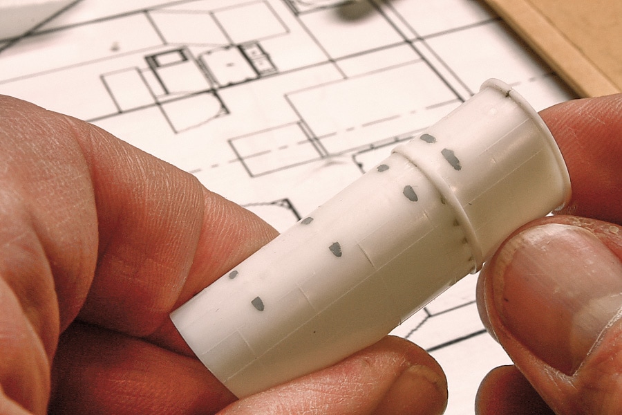
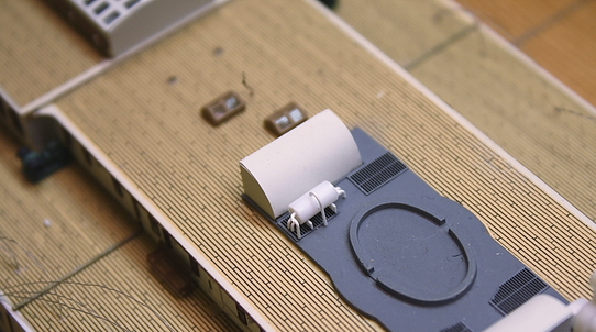
Right: a scratchbuilt water tank on the No. 1 funnel casing. |
|
Below, a steam escape pipe after installation. Each pipe had to fit behind and inside the braces of the photoetched ladder.
An added measure of realism was the simulated rivets. Altogether there are about 9,600 between the four funnels. These were made by lightly pricking the surface of the plastic on either side of the plate lines with the point of a very sharp awl. Although the real rivets were upraised, the visual effect was identical. One feature cast into the original parts that was not re-done was the band between the buff- and black-painted sections of the funnels. On the real ship this band was much narrower and lower in profile, but after much experimentation on spare parts it was decided that it was impossible to remove these or reduce them without damaging the finely upraised lines between the steel sheets which were essential to a realistic appearance.
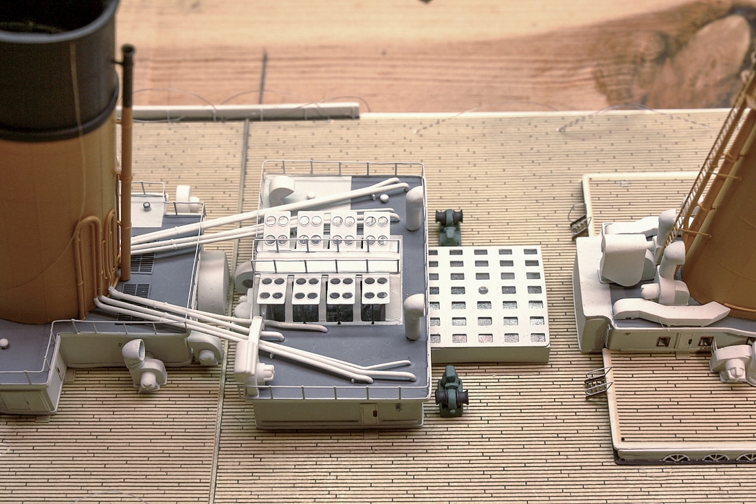
Above: the complex arrangement of pipes leading to the Tank Room. All the pipes had to pass under the railings and three had to pass under one of the ventilator ducts. The length of each pipe and the angles had to be precise in order for all to fit properly side by side.
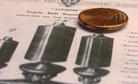
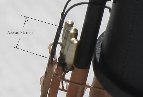
Several years later, just before the funnels were erected on the model, four sets of whistles were machined from fine brass rod. These were manufactured precisely to scale, with the branch piece at the base manufactured from styrene plastic.
|
|
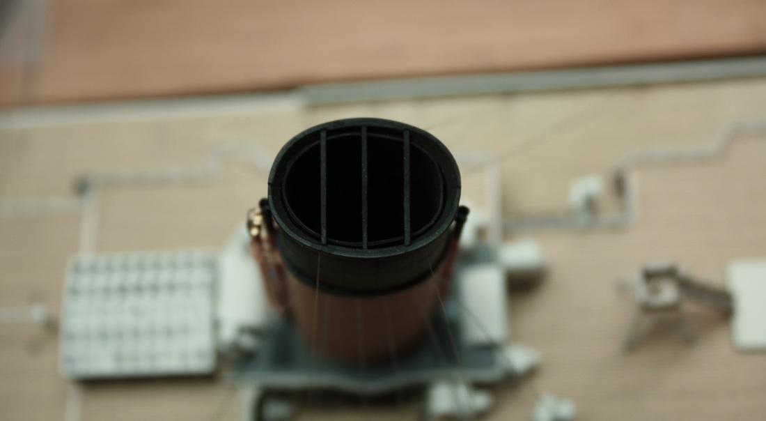
After all the rigging was in place, the tops of the funnels were detailed with the struts and other features . The insides of the funnels were painted with flat black paint prior to installation, as were the tops of the funnel casings. AIM Weathering Powder in "Soot" color was applied to the insides of the funnels and the funnel casings and around the top of the funnels, with a vacuum nozzle held nearby to prevent excess powder from falling onto the rest of the ship.