|
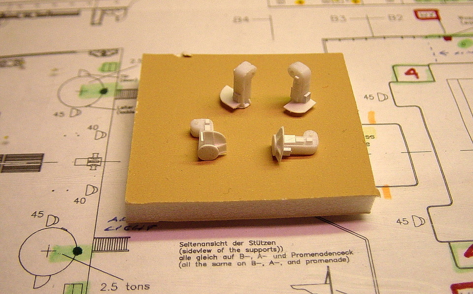
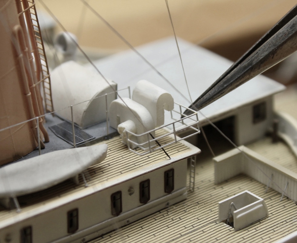
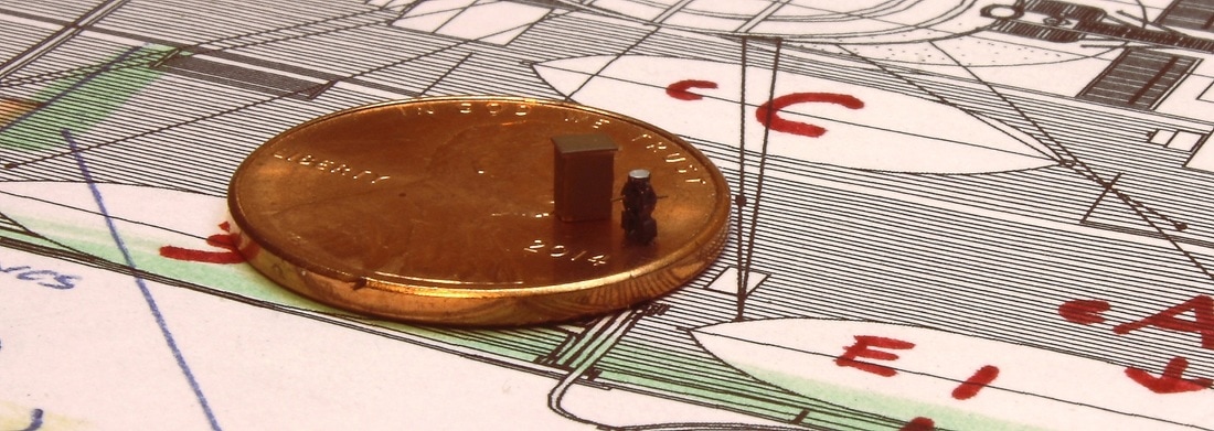
The true satisfaction in building this model was from achieving a level of detail that most modelers would consider impossible in this scale. To start, many of the kit pieces were replaced with finer, thinner alternatives made of photoetched brass - several sets are available specifically for Titanic. These supplied the kit's window frames, deck benches, crane jibs, railings and many other fittings. But many aren't available in photoetched brass and in some cases aren't detailed or accurate enough. Some fittings, like the portable telephone box at right, don't exist as a kit part and had to be built from scratch. On this page are some of the smaller parts that were enhanced or manufactured by hand, as well as many ways in which photoetched brass was used.
|
|
Deck plan detail in image above and both images below from the Hahn Titanic Plans - used by permission of Robert Hahn.
When this project started, I never had a master plan for scratchbuilding so many parts. I would just pick up a piece from the kit and think "that's a bit out of scale, I can improve on that" - and I'd look for a way to make it out of something else. After doing this a few times, I started looking at everything to see how it could be improved. In the end, most parts were rebuilt or replaced.
|
|
|
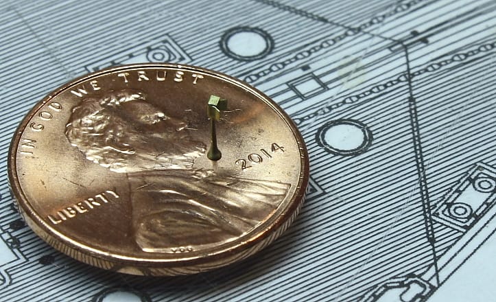
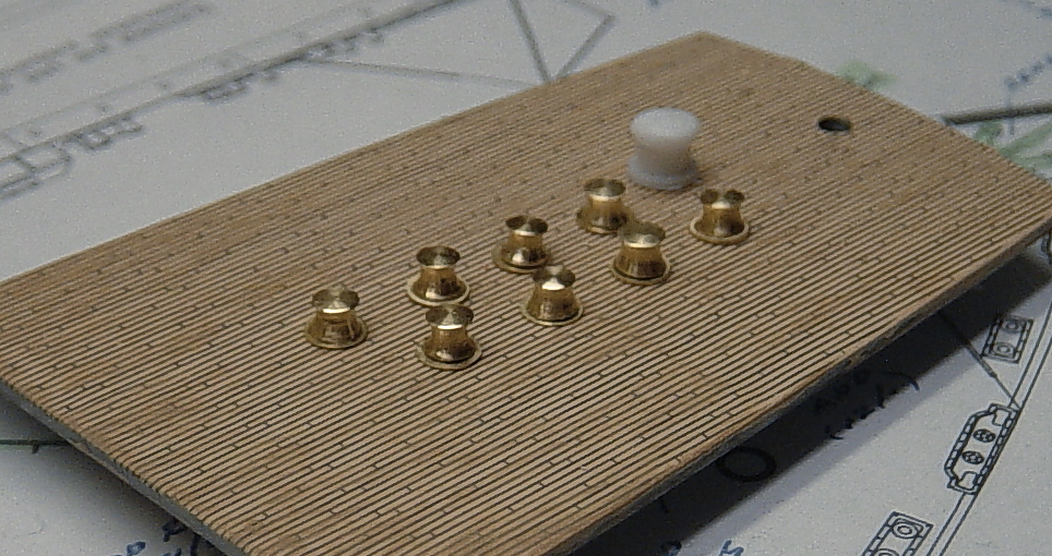
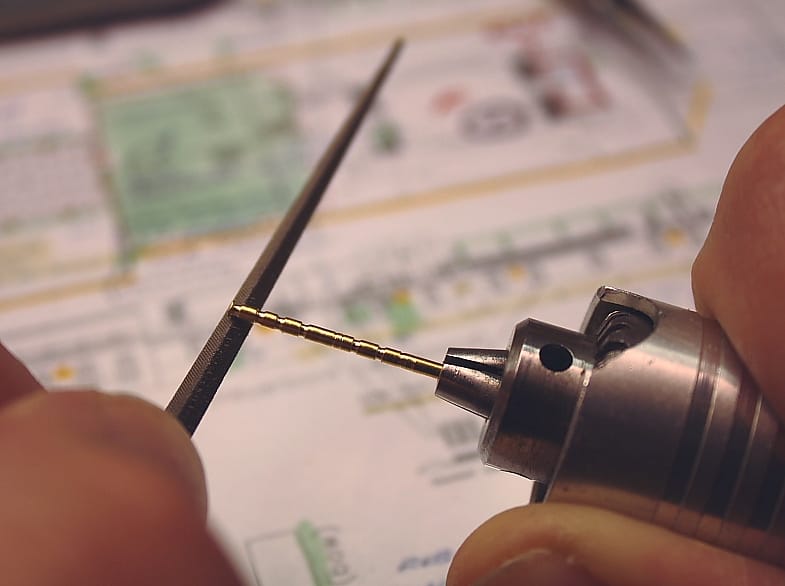
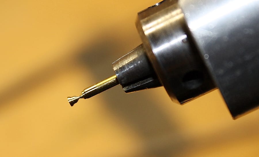
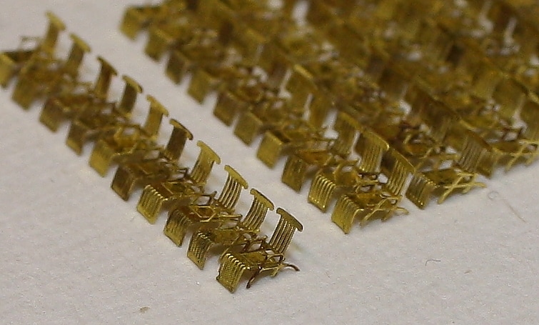
The capstans (above) were the earliest sets of fittings manufactured for this model. These huge drums were found at the forward and after ends of the ship and had a unique shape not replicated by the styrene kit part. The cast kit parts were also too large (one sits at the back). Their replacements were manufactured by spinning a brass rod in a jeweler's rotary-shaft tool held in one hand, and shaping the pieces by applying files of various shapes in the other hand (the same principle as a lathe). After shaping multiple pieces, each was cut off with a rotary disc. Above left, the finished capstans sit in front of the cast styrene kit piece. The same technique was used to manufacture the ship's bells (right).
|
|
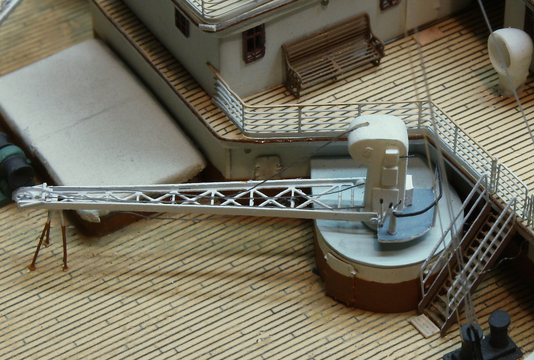
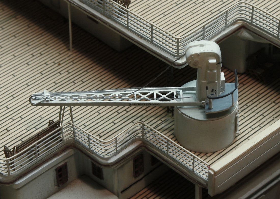
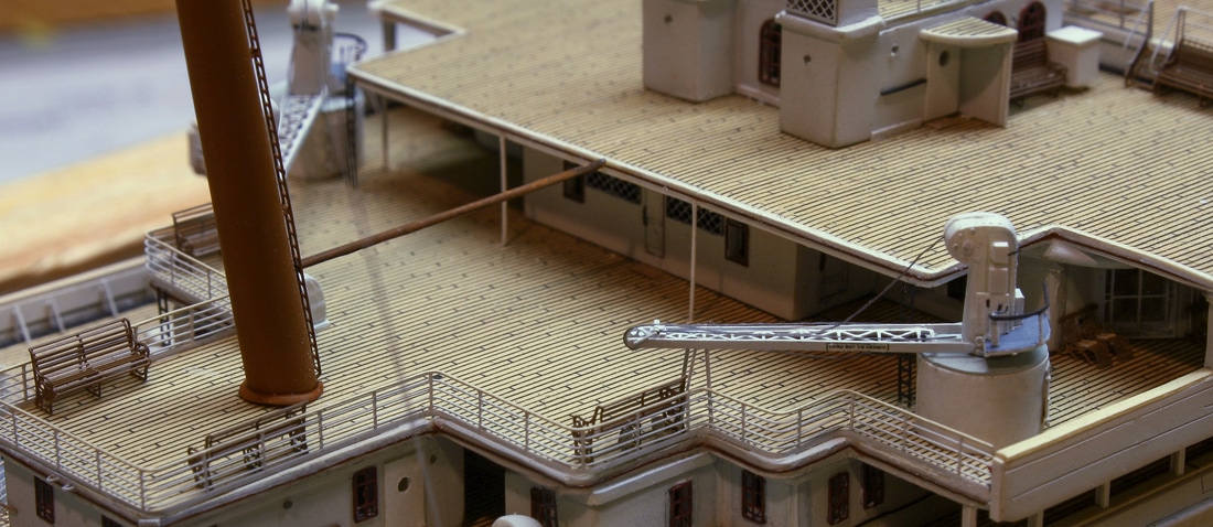
The cargo cranes were an example of using basic kit parts as the foundation and then rebuilding them with new or added detail (the funnels are another example). With the cranes, everything was cut off the masts, after which new operator's platforms, electrical junction boxes and other components were added. Rivet details were added to the masts with a fine awl.
Background detail above from the Hahn Titanic Plans. Used by permission of Robert Hahn.
|
|
|
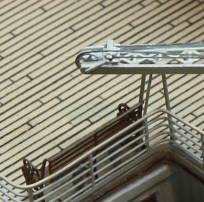
Railings for the operator's platform were made from photoetched brass, as were the hand levers, foot pedal and control handle on the railing post. The sides of the jibs were cut off and re-attached to give the jib an I-beam configuration. The sheave and associated parts at the ends of the jibs (photo at right) were made from scratch, and the crane hooks made three-dimensional by repeated applications of CA cement. (The one in the above right photo is just visible beneath the jib above the edge of the crane base, hooked to the underside of one of the cross members.)
To improve the appearance of the crane bases and give them sharp corners at the top and bottom edges, they were sheathed in .005" sheet styrene with a top of .010" styrene cut to the exact shape of the base. The doors are photoetched brass from a sheet of watertight doors for naval ships. |
|
The photos above also show some of the deck details, including one of the photoetched deck ladders (stairs) and railings. The top rail is painted to simulate teak. The brown nosing along the deck edge was replicated with brown flyting thread.
|
|
In some cases the photoetched brass pieces were modified for accuracy. One example is the grating above the front and sides of the anchor well at the bow (far left). The photoetched grating is in one piece, whereas the grating on the actual ship was in three sections with the one at the bow elevated above the sides. Another example is the fidley grates on the forward end of each of the first three funnel casings. The inboard corners of the forward two were angled. These were modified by cutting off the corners and cementing on a new edge piece of the correct length cut from a spare piece of photoetched brass. This type of situation occurred at every point through the build and the decision process was the same each time: Is it historically accurate? And is it to scale? If not, can I modify it to make it work? Or do I need to make one from scratch?
|
Below left: narrow pieces of photoetched brass were used as stanchions, and given a wire rope lifeline made of grey 8/0 nylon flytying thread. Below right: The inside of the well deck bulwarks were scribed to replicate the lines of the hinged cargo loading panels and the wash ports. Halfway along the bulwark at left there are three gooseneck vent pipes just visible; these ventilated some of the water tanks located in the ship's double bottom. They're made of Nitinol wire. Brass stanchions were also added to the inside of all the bulwarks, which were tapered toward the top to give a very narrow edge.
|
|
Spare pieces of photoetched brass, cut from whatever extra parts were handy, were used for many other applications such as stanchions, telegraph handles, binnacle parts, and extremely small detail components for scratchbuilt fittings.
The three photos below show some of the P/E brass railings and deck ladders (stairs) that were used all around the ship. All were cut from flat sheets and bent into shape. The railings were particularly difficult because of the corner bends that have to be spaced exactly the correct distance apart. Mistakes were made and discarded; another reason to purchase extras.
|
|
The above photo also shows the brown nosing along the after edges of the decks, simulated by cementing brown flytying thread with CA cement. Afterward it was coated with DulCote to elimiminate the glare (as was done to all areas of visible CA cement).
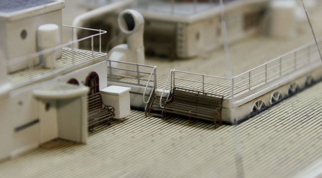
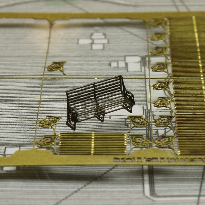
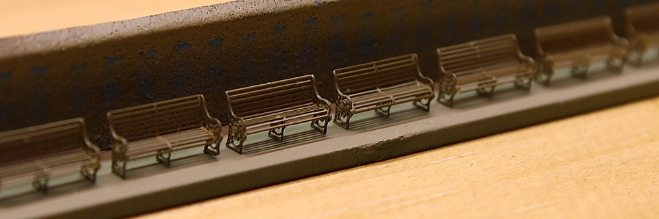
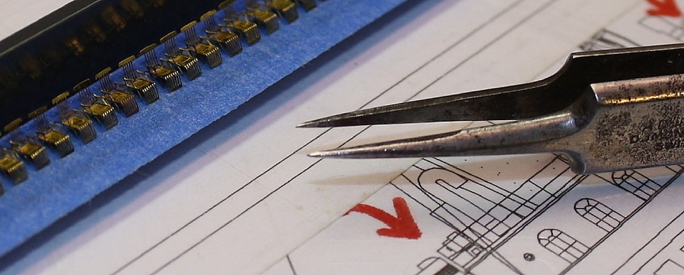
Deck chairs and benches were also assembled from photoetched brass parts. The seats and backs of the deck benches, cut from flat sheets or "frets", were given accurate curves by bending them against a jig made from a piece of styrene stock.
|
|
|
Two manufacturers produce benches for Titanic models in 1:350 scale; the ones from Tom's Modelworks were used on this build.
The most difficult thing was not assembling or shaping the benches (although adding the center support is particularly difficult) - it was imparting exactly the same bends to each. On the Poop Deck, there are benches placed back-to-back and end-to-end, so each had to appear identical to its neighbors. Extras were made and the mismatches discarded
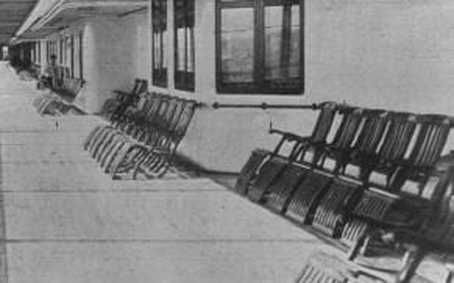
The benches were relatively straightforward to assemble, but the deck chairs were much less so. The photoetched ones are intended to be assembled fully extended, whereas on the ship when they weren't in use the forward end was folded down against the deck and the seat tilted up slightly (below right). This changed the whole angle of the chair and its legs from the fully extended position. The difficulty with replicating the chairs this way is that the one-piece legs, armrest and base wouldn't permit this configuration. These parts had to be cut and bent to achieve the position shown in the black-and-white photo.
|
|
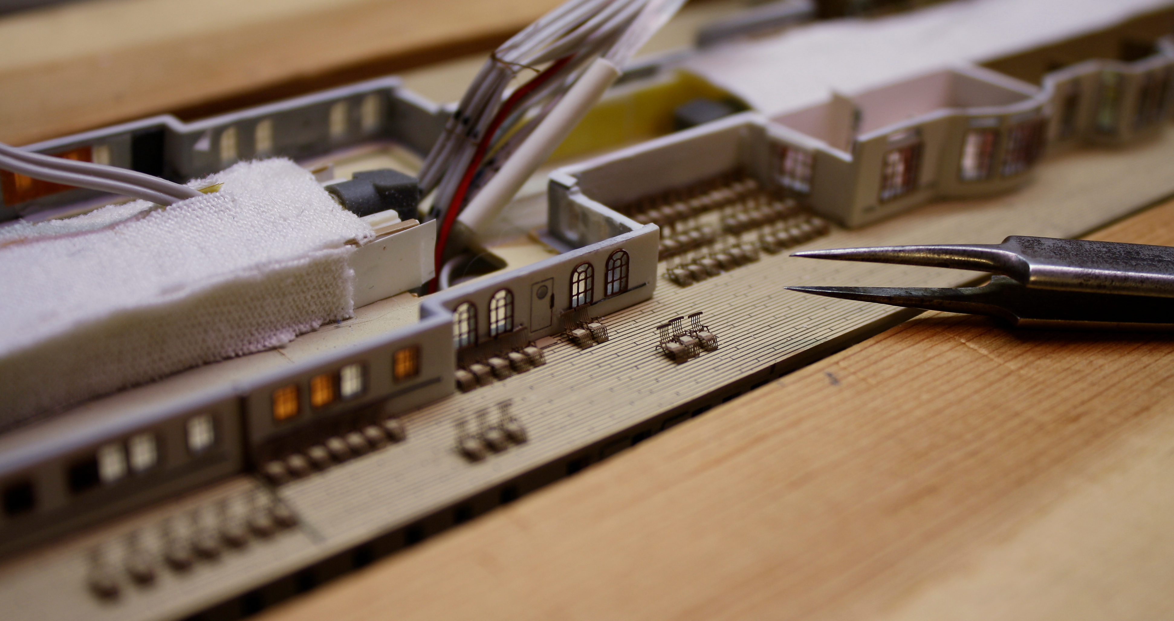
595 deck chairs were assembled, exactly the same number that were on the real ship, and placed in their exact locations corresponding to numbered positions*. Tom Harrison of Tom's Modelworks made a special order of 800 chairs for this model before his passing in February of 2009.
*There were actually 613 numbered positions - there was no number 13 - but the 18 against the after Promenade Deck bulkhead (on either side of the sliding doors of the Verandah Cafes) were not set up by the time Titanic arrived at Cherbourg.
*There were actually 613 numbered positions - there was no number 13 - but the 18 against the after Promenade Deck bulkhead (on either side of the sliding doors of the Verandah Cafes) were not set up by the time Titanic arrived at Cherbourg.
Background drawing from the Hahn Titanic Plans. Used by permission of Robert Hahn.
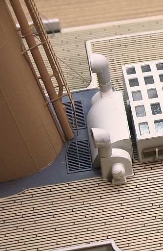
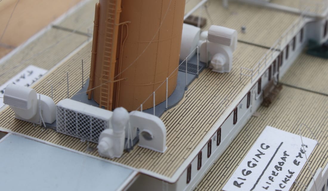
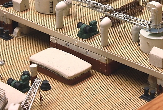
The ventilators on the model - thirteen of which can be seen in the photograph below - were all heavily modified or rebuilt from scratch in order to achieve the correct configuration and scale size. Historical photographs have revealed numerous differences from the styrene parts in the kit, which were based on the ventilator's from Olympic when the kit was first designed. An entire winter was devoted to modifying all the vents. All the cowls (air intakes) were hollowed out and their interiors painted with lightproofing material, then grey paint. The cowls on the real ship had a fine mesh grille over the openings, but this wasn't replicated since nothing fine enough could be found to replicate those grilles without giving them the appearance of being solid.
As noted on the Build page, all the stokehold ventilators were rebuilt from sheet styrene and a hollow void created underneath it so that you can see down into the opening under bright lighting conditions.
Note: this photo was taken before soot-colored weathering powder was applied to the deckhouse roofs, the tops of the funnel casings and the ventilators located there. These areas on the real ship would never have been as clean and pristine as they appear here.
MODELING RESOURCES - click for links______________________________________________________________________________________
|
Note: the above is not the complete list; many more have been found since it was compiled. Unfortunately all information posted
about subsequent changes were lost when the Titanic Research and Modeling Association (TRMA) website went offline in April 2018. On this model Rivet Counter Vent Inventory was used as a reference for changes only; most of the necessary modifications were made to a greater level of detail using my own methods. |
|
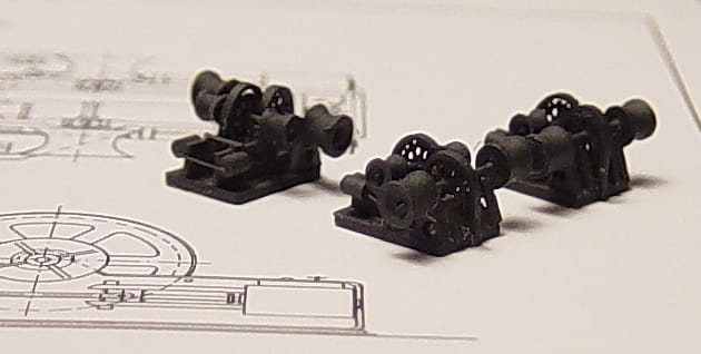
Of the things that were not available in photoetched brass and had to be scratcbuilt, some had to be made from more than one piece. The steam-powered winch assemblies, shown below left, are examples of this - each has 32 parts. The warping drums were machined from styrene rod the same way as the capstan drums above. Some details required a certain inventiveness: as there was no styrene rod available with a small enough diameter to replicate the piston rods, a hair from one of my Labrador Retrievers was used. The fine tips of Lab hairs were also used to replicate the protective bars over the sidelights facing into the after Well Deck, below (below right, above the edge of the canvas-covered cargo hatch).
|
|
Background drawings in above left image from page 73 of RMS Titanic: A ModelMaker's Guide by Peter Davies Garner. Used by permission.
|
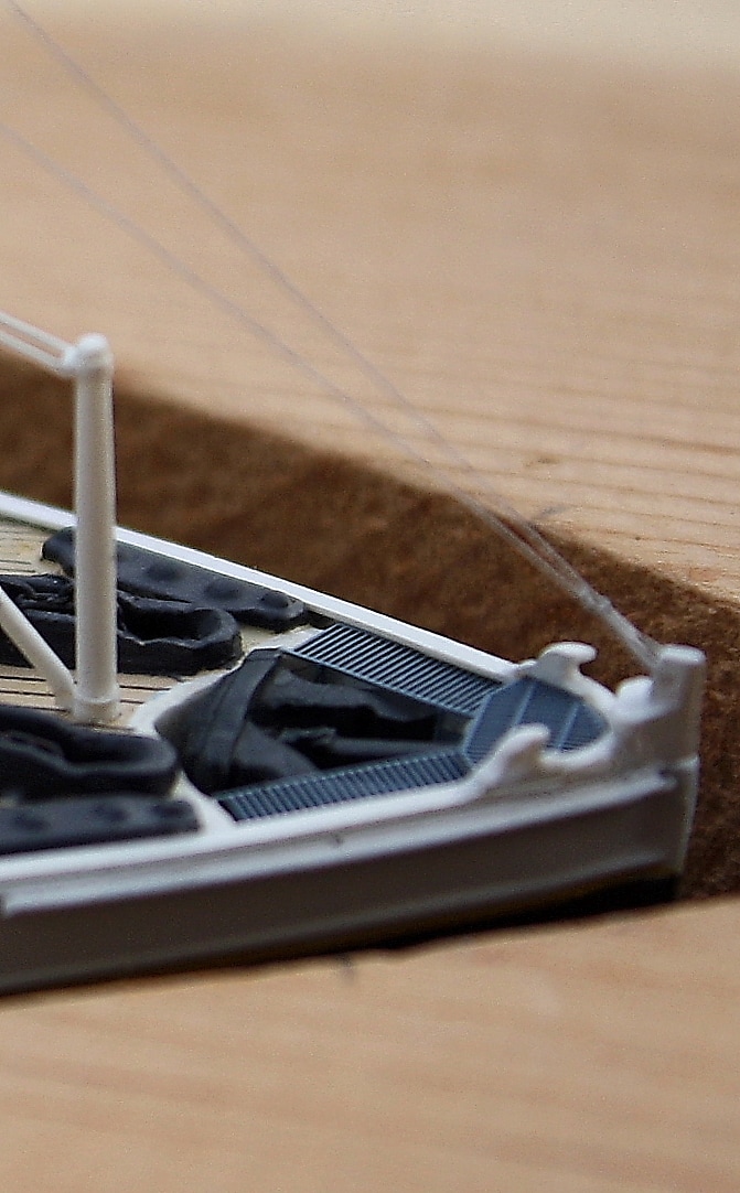
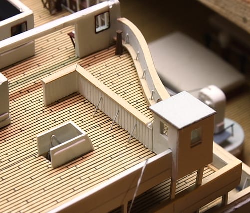
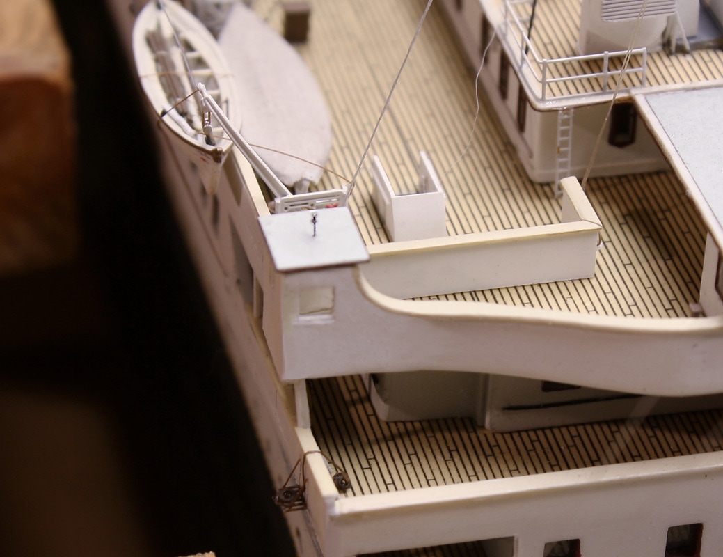
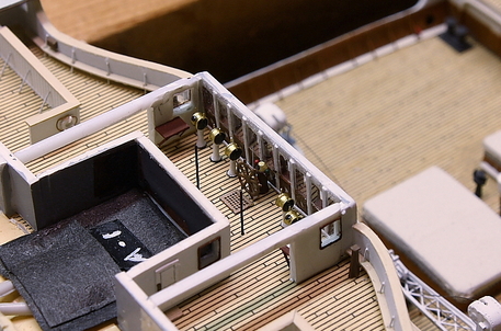
The Bridge wing cabs (left) were rebuilt entirely from scratch in order to give them sharp corners and edges, and have acetate sheets inside the window openings. The stanchions below the wing cabs, resting on the rail below, are not yet permanently in place in this photo which is why they appear to be leaning inward here. The bulwarks forward of the stairwells were made from .25 mm grooved styrene sheet to simulate the tongue-and-groove wood. On the forward bulwark overlooking the Well Deck, the curved footboards and top rails - made from sheet styrene - had to be cut to fit the curves of the bulkhead. The stanchions on the forward bulwarks are drilled through the footboard. Near the side window is one of the scratchbuilt pelorus pedestals, and just inside the opening to the Navigating Bridge the corner of one of the chart tables is visible. (This picture was taken before the one on the Interiors page, which shows all the telegraphs in place.)
|
|
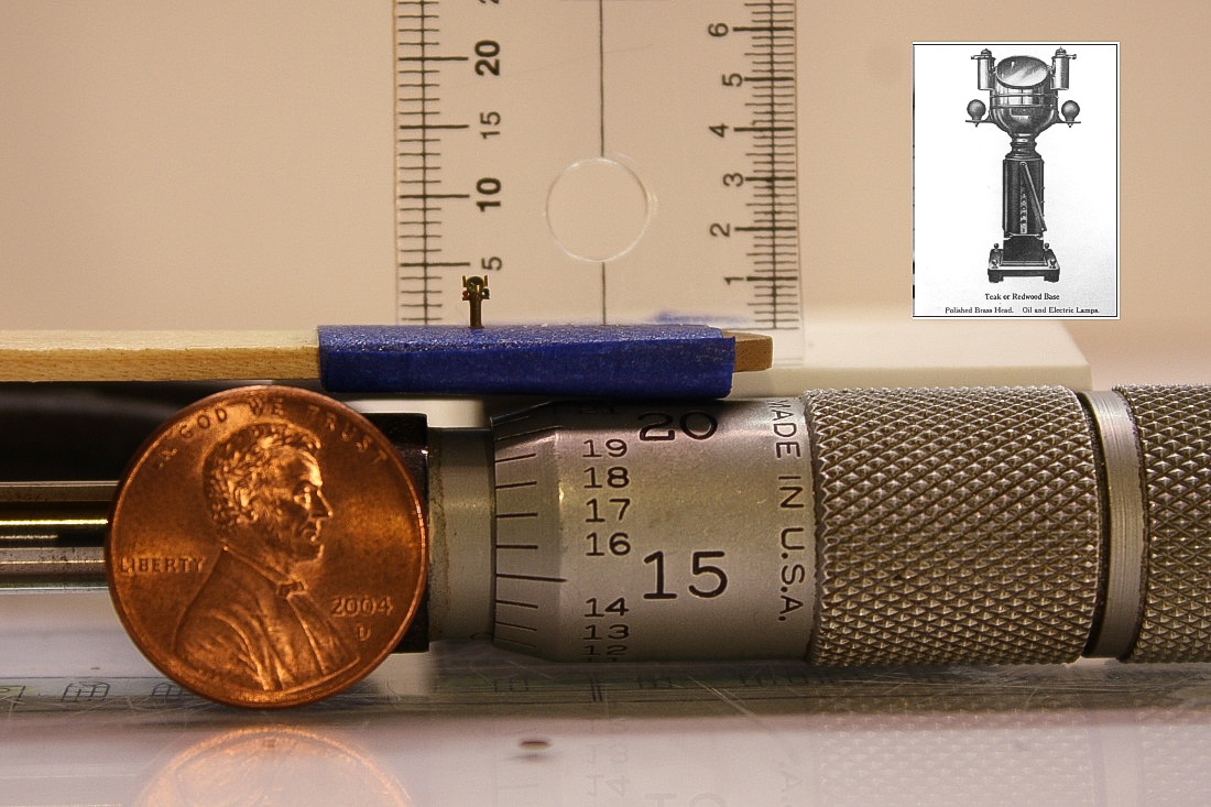
Near the very end of the build, the Morse lamps were built and mounted in the center of the wing cab roofs (left). The cylindrical lenses were cut from .25mm fiber optic strands and mounted between two tiny discs cut from spare photoetched brass. The supporting post for each was cut from a strand of .004" nickel-titanium (Nitinol) wire: just under 1-1/2" dia. in scale. The coils of rope on the leadsman's platform and on deck were made from tightly wrapping brown 8/0 flytying thread around the tip of a sharp awl, then applying a light amount of fast CA cement. That made the thread rigid enough to stay coiled tightly when slipped off the shaft of the awl. Then a second amount of CA cement was lightly applied and the loose coils gently pinched together with the tips of a fine pair of tweezers. A touch of Dullcote (flat lacquer) applied with the tip of a fine paintbrush removed the sheen. |
|
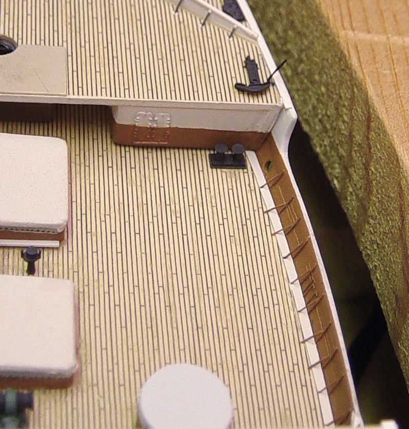
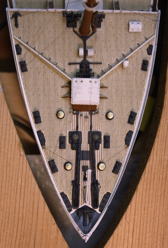
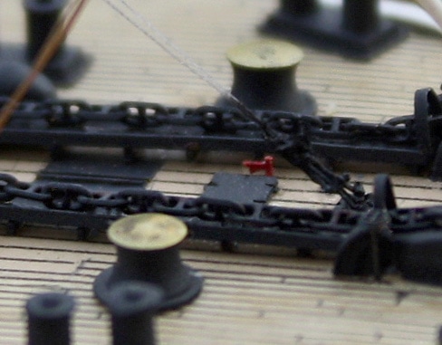
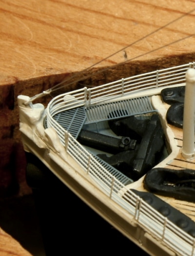
On the Forecastle Deck (right), almost everything with the exception of the cargo hatch and a few other components was replaced and/or rebuilt from scratch. This included the breakwater angling back from either side of the cargo hatch; the one cast into the deck piece of the kit was at the wrong angle, and was cut off and rebuilt from styrene sheet. The solid cast chain races were also removed and replaced with new ones that were elevated above the deck. The anchor chains in this photo had not been weathered when this photo was taken; later they were dry-brushed to simulate rust.
This deck, being a working deck planked with pitch pine, appears slightly darker and was dry-brushed in random places to appear dirtier than the 1st and 2nd Class passenger decks. The deck area between the chain races, on either side and back to the cargo hatch are detailed with wider-spaced plank lines and a teak color to simulate the difference in the deck sheathing here. Creative thinking can often solves many modeling problems. Solutions can often be found by using parts intended for other purposes: the steam valve wheels (just below the cargo hatch in the center) were cut from a sheet of photoetched brass railroad brake valve wheels. The posts for the valve wheels were cut from brass belaying pins left over from a whaling ship model. The watertight doors in the well decks and on the crane bases are from a set for naval ships. Conveniently, the same set also contains hydrants which, once the hose reels are cut off, work very nicely for Titanic (below, painted red, between the chain races). |
|
|
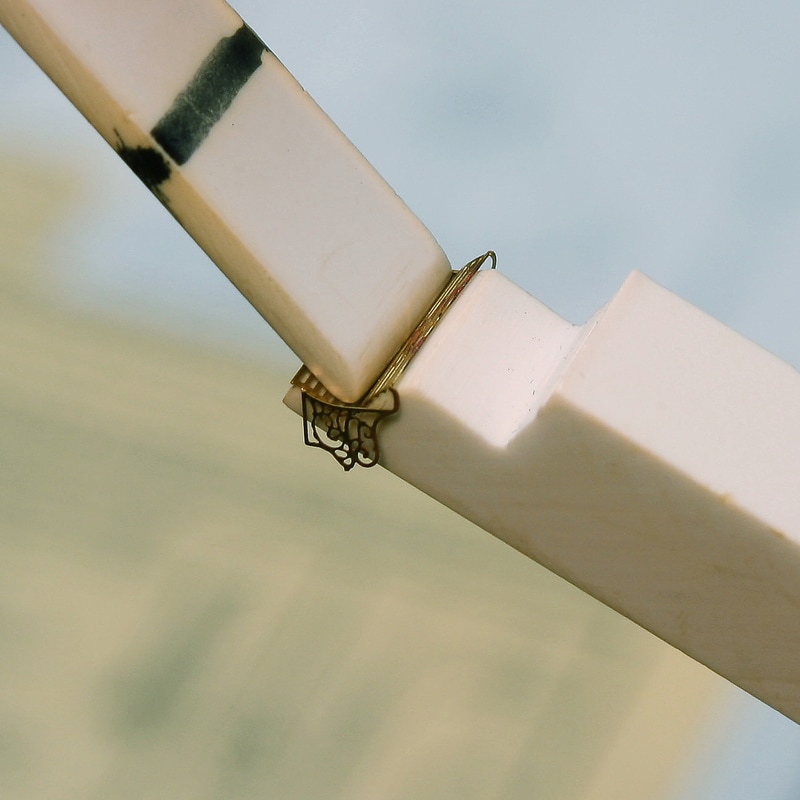
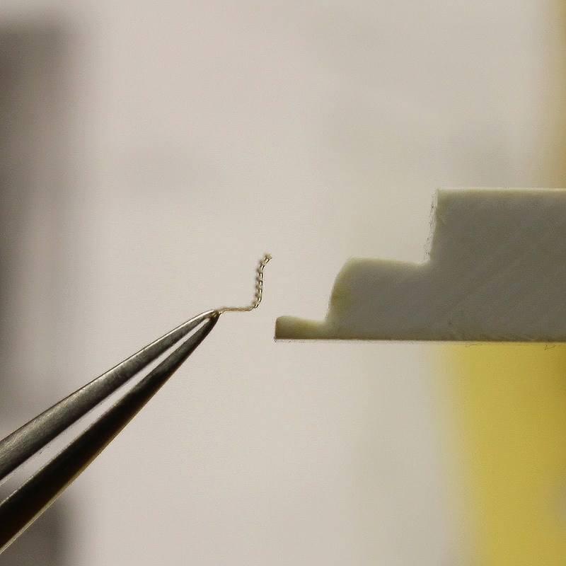
The best example on this model of adapting one thing for another, though, is the anchor chains. Stud-link chain could not be found in the correct size from any modeling supply company, so another source was used. They're literally worth their weight in gold, as they're cut from a 14-karat solid gold necklace. ("Stud link" is a standard chain style in the American jewelry industry).
The center anchor that comes with the kit is too small, so a new one of the proper size (below right) was carved from built-up styrene stock, and a shank and lifting ring added. After it was finished, it was dipped in paint and allowed to drip dry to give it more of a cast-steel appearance. The anchor well then had to be made longer and deeper to accommodate it, matching the dimensions on the real ship. |
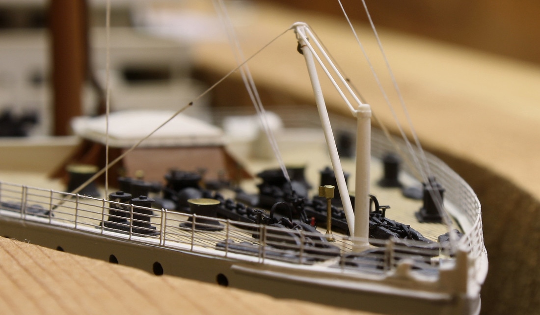
The anchor crane (below left) was made from four sizes of styrene rod, with all details accurately replicated including the large block at the end of the jib that's secured back to the jib with a strap. The mast has a slight taper, just like the real one. Both photos below also show the fairleads at the prow, carved from built-up styrene stock in the same manner as the center anchor.
|
|
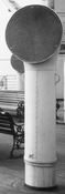
Note: the portable phone box just to the left of the anchor crane has two swing-out doors (see the image at the top of this page). It was constructed based on an early Olympic photo. Sometime after this, an enlargement of a Titanic photo at Queenstown revealed that Titanic's phone box on the docking bridge had a single door. Based on this, the phone at the bows may have had a single door also. I could have built a new one to replace it, but it was so well made that I elected to leave it as is. The other two phone boxes on the model - on the docking bridge and in the crow's nest - were built later and each have single doors.
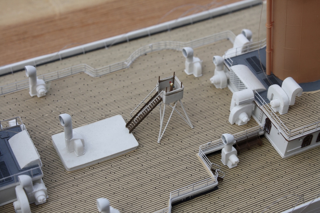
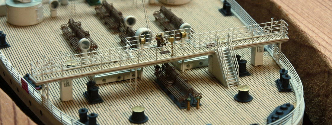
The compass tower (below) is another item built entirely from scratch. This is my favorite scratchbuilt piece on the entire ship. Although this structure is available as a photoetched brass replacement that makes up the platform once bent into three-dimensional form, the legs and struts would have appeared flat and certain details were missing. Instead, one was made from styrene sheet and rods except for the photoetched brass ladder (stairs). The canvas windbreak, which can be seen folded down around the four upright corner posts, was made from plastic kitchen wrap and painted to a canvas color. Even under extreme magnification, it stands up to scrutiny and presents a highly realistic appearance. It's the crown jewel of the Boat Deck.
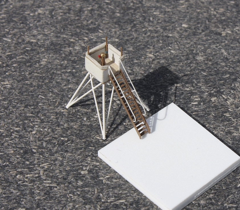
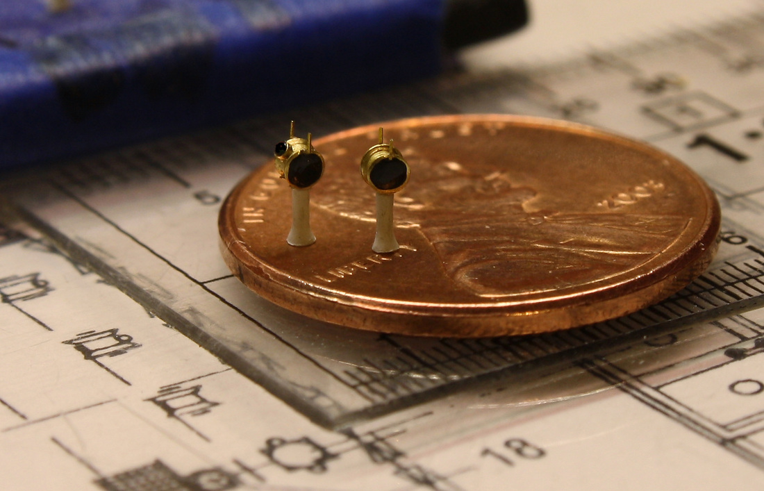
The binnacle in the center of the platform above is only 3mm tall and is made of 11 separate parts. It's an exact scale replica of the real one. Below is a similar one made for the Docking Bridge on the Poop Deck. The most difficult thing about building pieces this small is that extremely fine pieces have the annoying habit of sticking to the tweezers with static electricity.
Engine-order telegraphs and docking/steering telegraphs (below) were machined from brass with posts made from styrene rod; the flare at the base was made by holding the tip of the styrene rod near a soldering iron for a brief second until the heat melted the tip outward. Background drawing in left image from page 94 of RMS Titanic: A Modelmaker's Guide by Peter Davies-Garner. Used by permission.
|
|
Below, two of these telegraphs on the rebuilt Docking Bridge. Two special details are the wooden chocks under the inboard ends of the flagpoles: they're cut from a block that covered the floor of the Engine Works at Harland & Wolff in Belfast; while it's unlikely that it's one of the same from Titanic's day, it's a link to her history nonetheless.
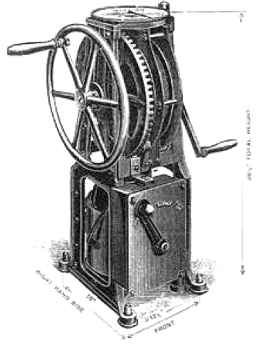
At the opposite end of the ship near the Navigating Bridge were two sounding machines. These paid out a long cable with a weight at the end for taking depth readings (soundings). The one on the port side was uncovered and ready for use when Titanic approached Queenstown, so it's logical it would have also been made ready at Cherbourg. The one below was made from spare photoetched brass, and the handles are made from .004" nitinol wire - making them perfectly to scale. The cover sits behind it. The sounding spars which held the cable out and away from the ship on each side (not shown) were made from .015" piano wire, tapered at each end with a fine whetstone. A coating of medium CA cement "primed" them so the white paint would adhere.
|
|
Ironically, with many small things like this the detail exceeds what can be discerned with the naked eye. Only in close-up photography enlarged quite a bit can they be appreciated. But they were fun to make, just to see how small I could go in detail.