In building this model, precision detail was achieved by borrowing some tools and benchwork techniques from watchmaking and jewelry work, trades going back three generations in my family. Growing up I worked in my father's business a bit - and perhaps the skill of working with a steady hand under magnification was inherited - but the key to success was hands-free magnification and good model-building ergonomics from start to finish.
The first step as soon as the hull was complete was to build a portable "drydock" to hold the model. Constructed of scrap wood costing less than $8.00 from Home Depot, it had two purposes: to provide a place where the arm and hand could rest at deck level, and with the cover in place, to provide protection for the model when it was not being worked on.
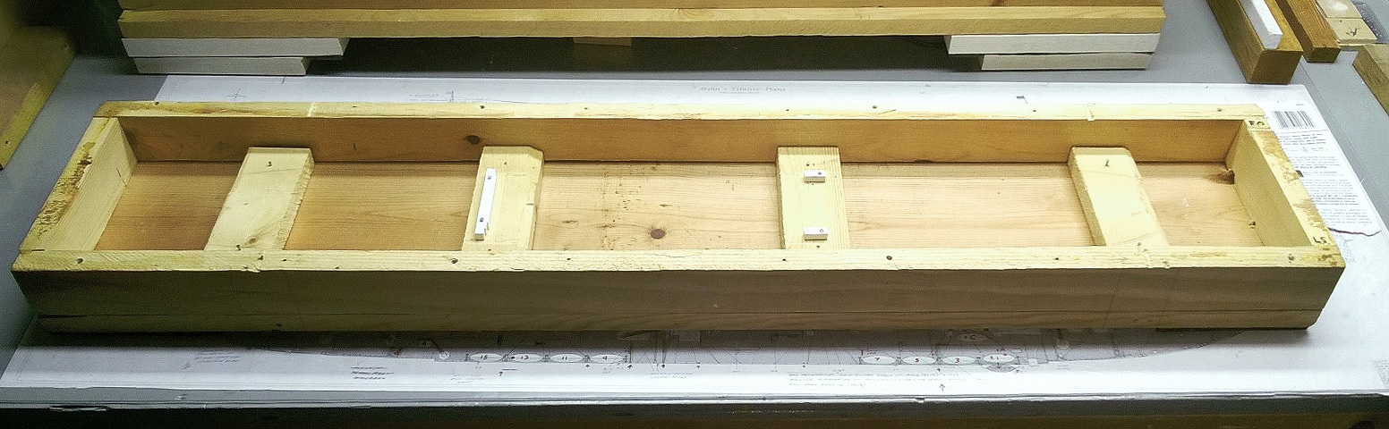
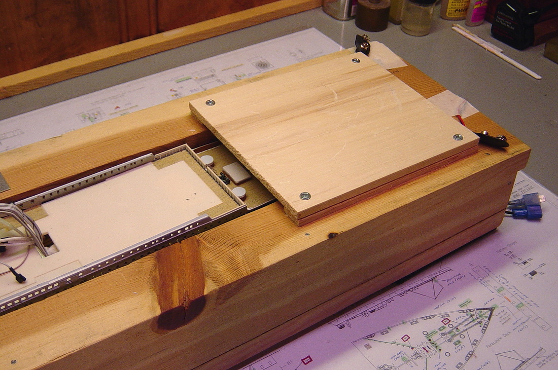
The wide top surface on either side of the ship provided a solid hand and arm rest for working up close as the superstructure was assembled and detailed. Removable screw-down panels covered the Fo'c's'le, Poop and Well Decks. These served as protective covers over these areas once they were finished, and provided additional hand rests for detail work on either end of the superstructure. Note the plans readily visible under the plexiglas work surface, which is ideal for cutting photoeteched brass. All drawings and plans visible under the work surface on this page are from the Hahn Titanic Plans. Shown on this web page by permission of Robert Hahn.
When the model was not being worked on, the cover provided physical protection as well as acting as a dust cover. As a side benefit, the cover provided extra bench space to lay out the numerous parts and pieces under assembly and in the process of being painted. By the later stages of the build a new and taller cover had to be made to accommodate the height of the masts. The cover was so sturdy it could have withstood a ceiling collapse.
|
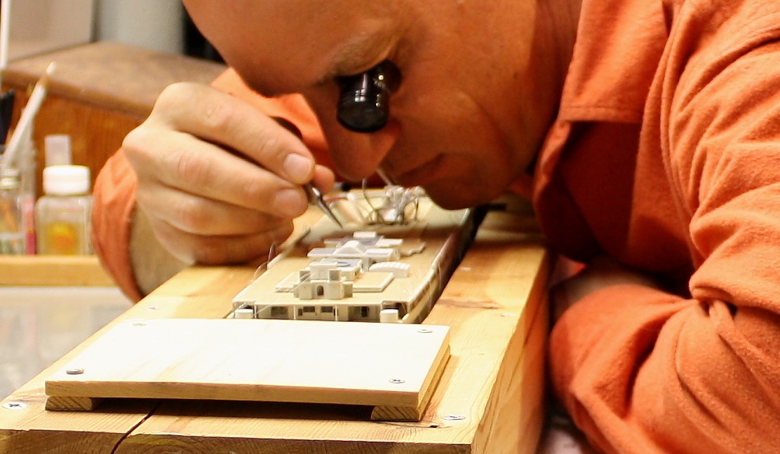
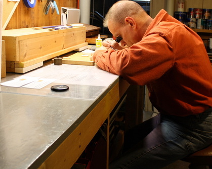
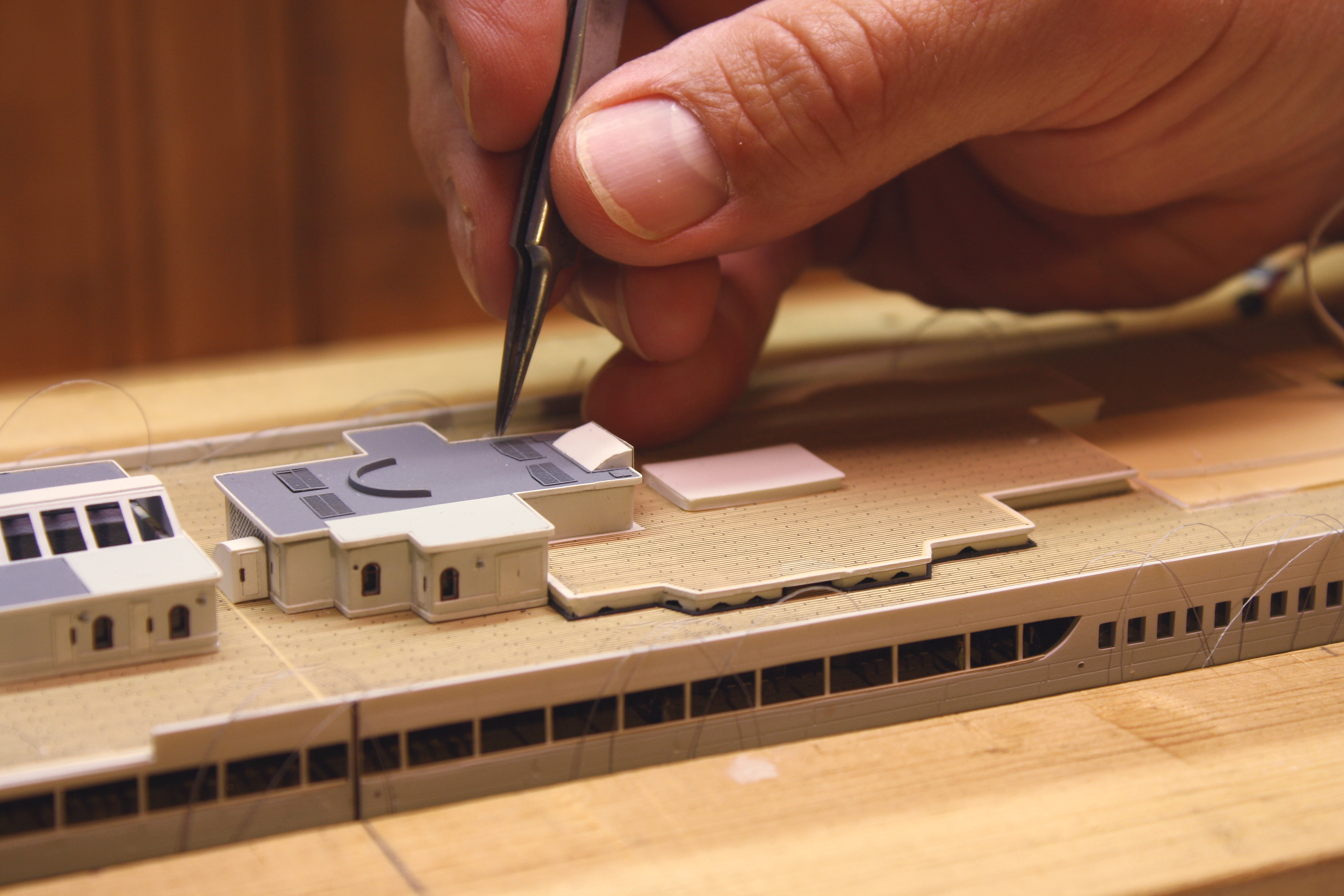
The photo at left shows the huge advantage of the "drydock" that the model sat in. For close-up detail work that had to be performed on the model itself, the drydock provided protection on all sides and provided a solid place to rest the heel of the hand. With the weight of the upper body, arm and wrist supported in a relaxed position, the fingers were the only things that had to move. Without tension transmitted from the forearm to the wrist, finely controlled finger movements were possible.
Hand support is everything in fine model work. Most modelers would be surprised at how much easier and more precise their work would be if they used a solid hand rest.
|
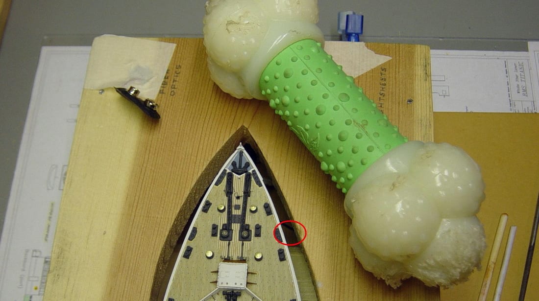
DOG BONE, RIGHT AHEAD!!
|
Despite the attention given to protecting the model, a near-catastrophe ocurred early in the build just after the Forecastle Deck was completed. The model bench in the basement of our home is located against the side of the open stairwell to the first floor. One evening a heavy dog bone bounced down the stairs, fell over the edge and dropped two feet onto the model while I was working on it. The drydock absorbed most of the impact, but the edge of the Forecastle deck was stove in and the shock caused most of the delicate fittings to fly in every direction. Almost all were recovered. It could have been worse. After that day, the stairwell opening above the back of the bench was covered with a heavy screen.
|
|
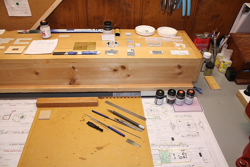
Ergonomics plays a big part in fine detail work. Proper bench height is critical to success. Working hunched over with the upper body unsupported imparts muscle tension to the neck and shoulders as well as strain on the lower back, and transmits that tension to the forearms - not to mention that the modeler's body in that position blocks overhead light. A relatively high work surface eliminates this. This is the same principle followed by watchmakers and bench jewelers. The standard watchmaker's bench is 38" high and a stone setter's bench is 40". The modeling bench in these photos is slightly higher at 42".
|
|
Understandably, not everyone has the room or resources for a bench of the type shown above. Some modelers have to make do with a kitchen table or small desk. Even these will suffice if adapted accordingly. Home Depot, for example, sells pre-cut pieces of smooth 1/2" plywood called "project panels" in 4 x 4 ft size, and will cut them down to 3 x 4 ft size at no charge. That's ideal for a kitchen table or desktop. A stack of books under each corner is all that's required to elevate it to the right level.
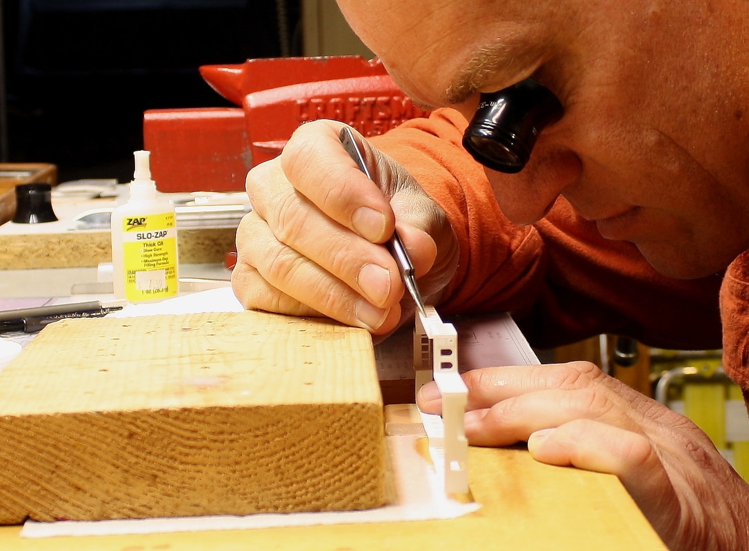
Below, a solidly positioned hand rest made work easy on a part that sat higher up off the work surface. By providing support for the hand and forearm, there was no tension in the wrist and palm that would have made it difficult to keep the fingers steady. (Scrap wood is free at Home Depot; a book would work just as well although you'd risk getting glue or paint on it.)
Below, a solidly positioned hand rest made work easy on a part that sat higher up off the work surface. By providing support for the hand and forearm, there was no tension in the wrist and palm that would have made it difficult to keep the fingers steady. (Scrap wood is free at Home Depot; a book would work just as well although you'd risk getting glue or paint on it.)
With proper hand support, the two fingers holding the tweezers should be the only parts of the hand that move. If it's not possible to rest the heel of the hand on something, the fourth and fifth fingers can support the two holding the tweezers (below).
A bridge (not shown) was also used for hand support; this consisted of a 3-inch-wide piece of 1/2" wood with two blocks under either end; it sat on either side of the drydock cover and spanned the space over the model to support the heel of the hand.
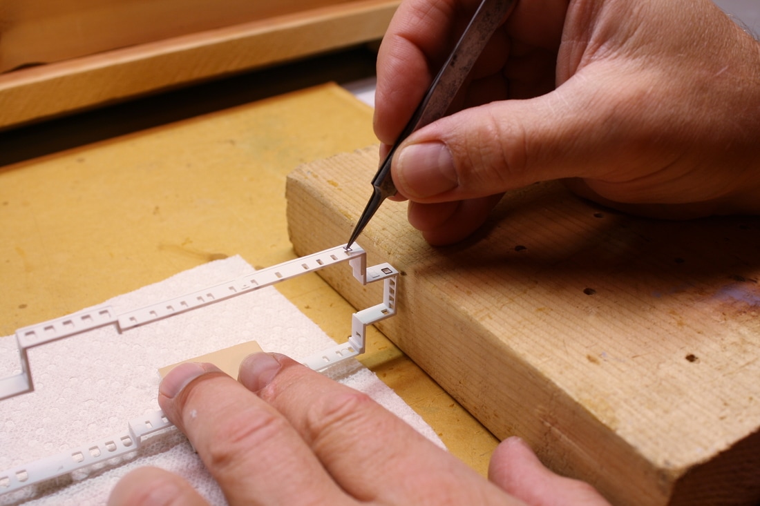
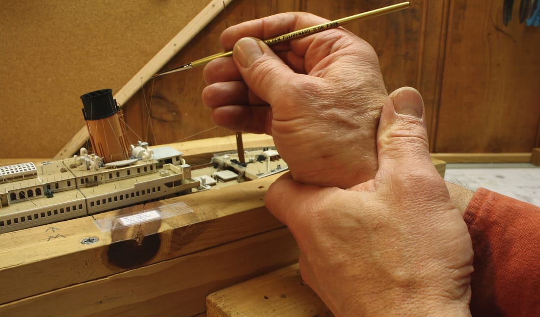
When it's not possible to bridge the model or rest a supporting digit on the deck - as in the later stages of the build when reaching further in from the sides - the detail hand can be supported by locking the other hand around the wrist (below). The index finger of the lower hand is also resting on the front edge of the drydock.
When it's not possible to bridge the model or rest a supporting digit on the deck - as in the later stages of the build when reaching further in from the sides - the detail hand can be supported by locking the other hand around the wrist (below). The index finger of the lower hand is also resting on the front edge of the drydock.
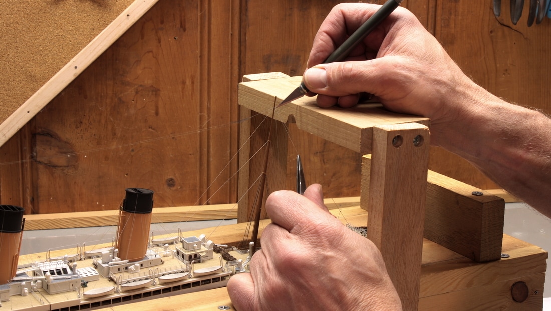
For rigging the Marconi array and the spreader stays, and doing other rigging work near the mastheads, bridges of 3/4" oak were temporarily screwed into place on the sides of the graving dock. These supported the hand for the precision work needed to rig these last and final details on the model. (Pine would have worked just as well; I just happened to have oak of the ideal size.)
|
Four "nevers" to avoid unintended damage or mistakes:
|
|
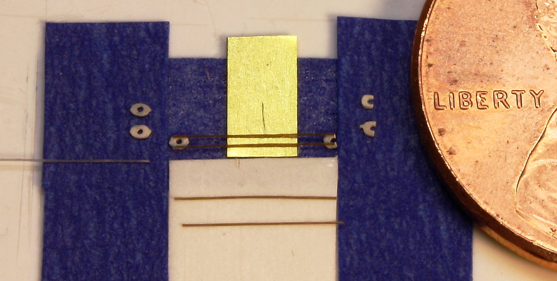
For producing identical parts in quantity, jigs are the answer. For assembly, a jig acts like a set of very small extra hands to hold parts. A jig can be made of nothing more than a few pieces of styrene plastic cemented together or, in the case of the "sticky jig*" at right (used for assembling the davit blocks and lifeboat falls) a few strips of tape on a piece of flat styrene plastic. Jigs like this are simple but indispensable. The assembly of the davit blocks could not have been accomplished without something to hold the tiny cheek pieces in place and prevent them from lifting up off the surface when the glue-tipped thread made contact with them.
|
|
It took awhile to come up with this jig, but eventually I hit on the idea of using tape. Later I improved on it by pressing a finger on the adhesive side several times to reduce the stickiness. Anytime you find yourself thinking "there has to be a better way", there probably is. That's what I realized when the first jig didn't work well. Mass production of small parts should be satisfying, not frustrating. (And after all, modeling is supposed to be a relaxing hobby.)
|
As a side benefit, a jig also gives much more uniformity in the finished results. This is especially true for a jig used to impart a particular shape or bend to a piece, as in the case of the davit arms - or deck benches (right).
*The name was borrowed from the term "sticky bomb" in the 1998 Tom Hanks film "Saving Private Ryan." |
|
Good tools cost a little extra, but are indispensable. They last a lifetime and make it much easier for the modeler to detail work on small parts and to fine tolerances. Below are the tools that I used and two sources for acquiring them
.
.
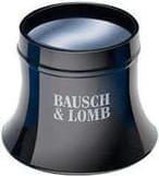
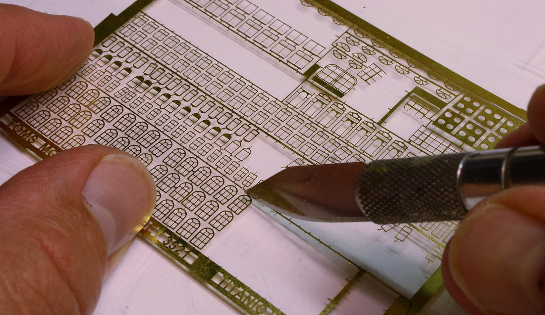
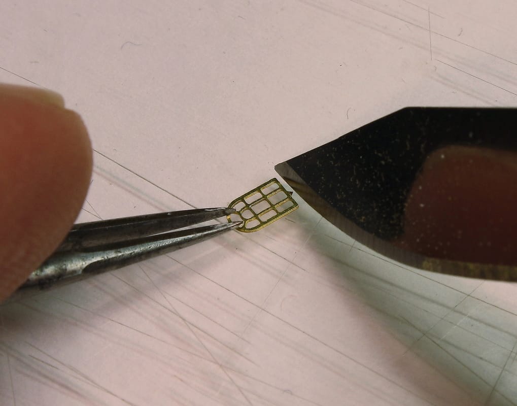
For close-up detail work, two jeweler's loupes were used: one of 3.3x magnification and another of 4x for very fine work. It's no exaggeration to say that it would not have been possible to build this model without them. Unlike binocular magnifiers or a lens on a flexible arm, a loupe held in front of the eye provides a perfectly clear sight picture with zero distortion or blurriness. 3.3 or 4x power may not seem like much magnification, but in practice it makes a big difference. Below is what a fret of photoetched brass windows looks like with the unaided eye viewed through a 3.3x loupe. A loupe can be hard for a beginner to hold in place without squinting, but watchmakers' supply houses also sell a wire headband for that purpose.
|
|
|
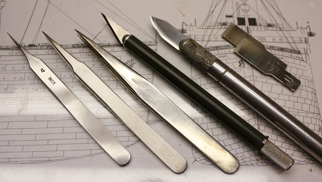
At right are some of the tools that were essential for this build. The first two are watchmaker's tweezers, the third a pair of general-purpose tweezers, then two X-Acto knives and a pair of X-Acto spade-tip blades. The larger X-Acto knife with the silver handle has a #25 'Large Contoured' blade and was used for rough cutting of styrene and trimming photoetched brass, and the smaller X-Acto knife is a 'Gripster' with a #11 'Classic' blade. It's surgically sharp and has a very fine point, making it ideal for cutting and trimming styrene parts to a tolerance of a fraction of a millimeter. The spade-tip blades were used by themselves without handles to bend photoetched brass and to shave (scrape) styrene pieces thinner or smoother.
|
|
|
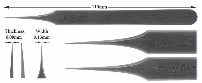
Watchmakers' tweezers are precision made and are essential for handling small pieces of photoetched brass. The ones most often used on this model for working with photoetched brass and other fine details was the No. 2 (second from left above), although the tips were filed to a slightly finer point than they're manufactured to. The No. 4 (leftmost one above, and at right from the Otto Frei website) was for extremely fine parts. The general purpose tweezers (third from right, above) was of the 'MM' pattern. |
|
|
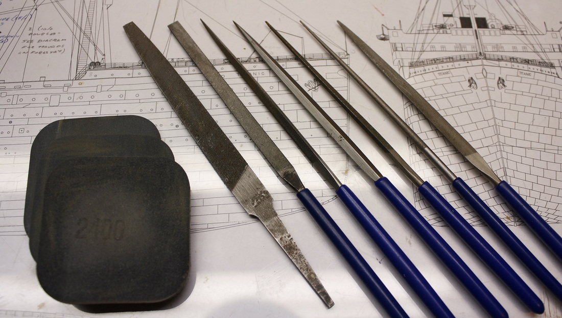
These are the tools that were used for filing, shaping and smoothing parts: a small bastard file for heavy filing, and a set of six files of various cross-sections with much finer teeth for shaping to a finer degree. As with all tools, cheaply manufactured versions are available, but typically the teeth are much coarser and can't shape or finished fine styrene plastic parts as cleanly. The double-sided sanding pads are perhaps the most useful things I've ever found. I went through two dozen of each. 2400-grit did rough sanding, 3200-finer sanding, and 4000-grit final smoothing. |
|
|
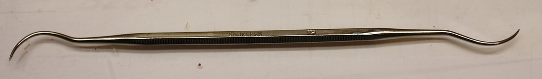
The tool at right is a panel scriber for plastic models. It was used to enhance the lines between the shell plating on the hull, and to scribe the lines for the removable ports and doors in the various bulwarks.
|
|
MODELING RESOURCES - Click for links______________________________________________________________________________________
|
Remember to support your local model railroad shop for paints, brushes, X-Acto knife blades, styrene stock etc.
|
|


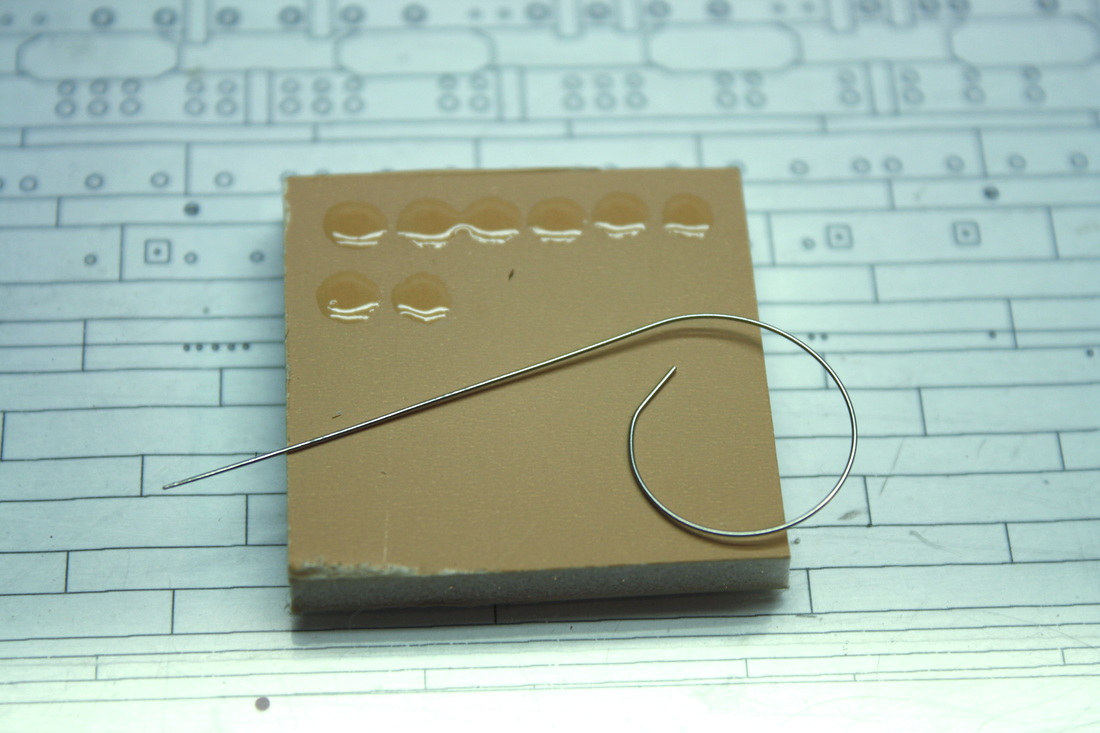
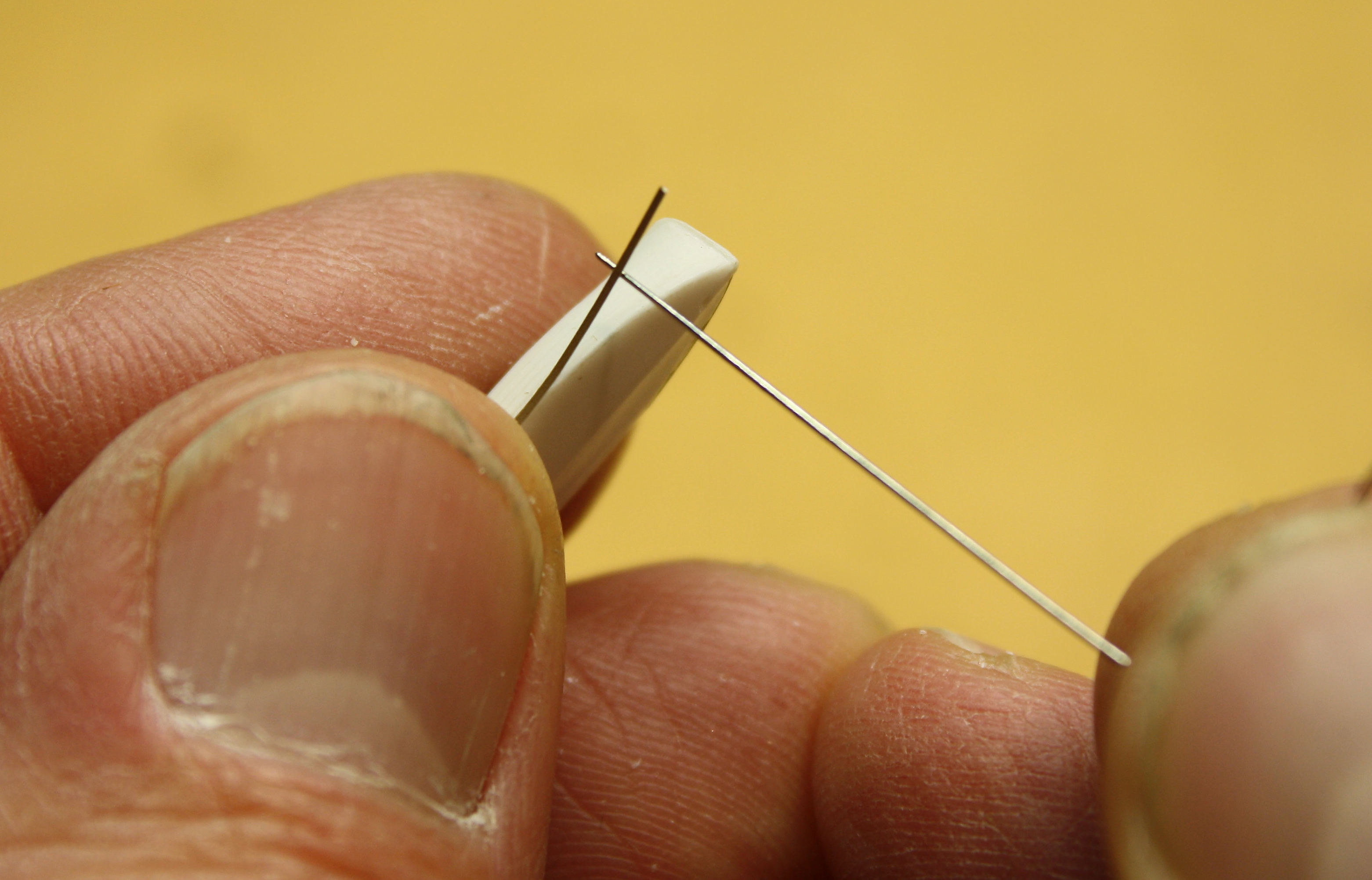
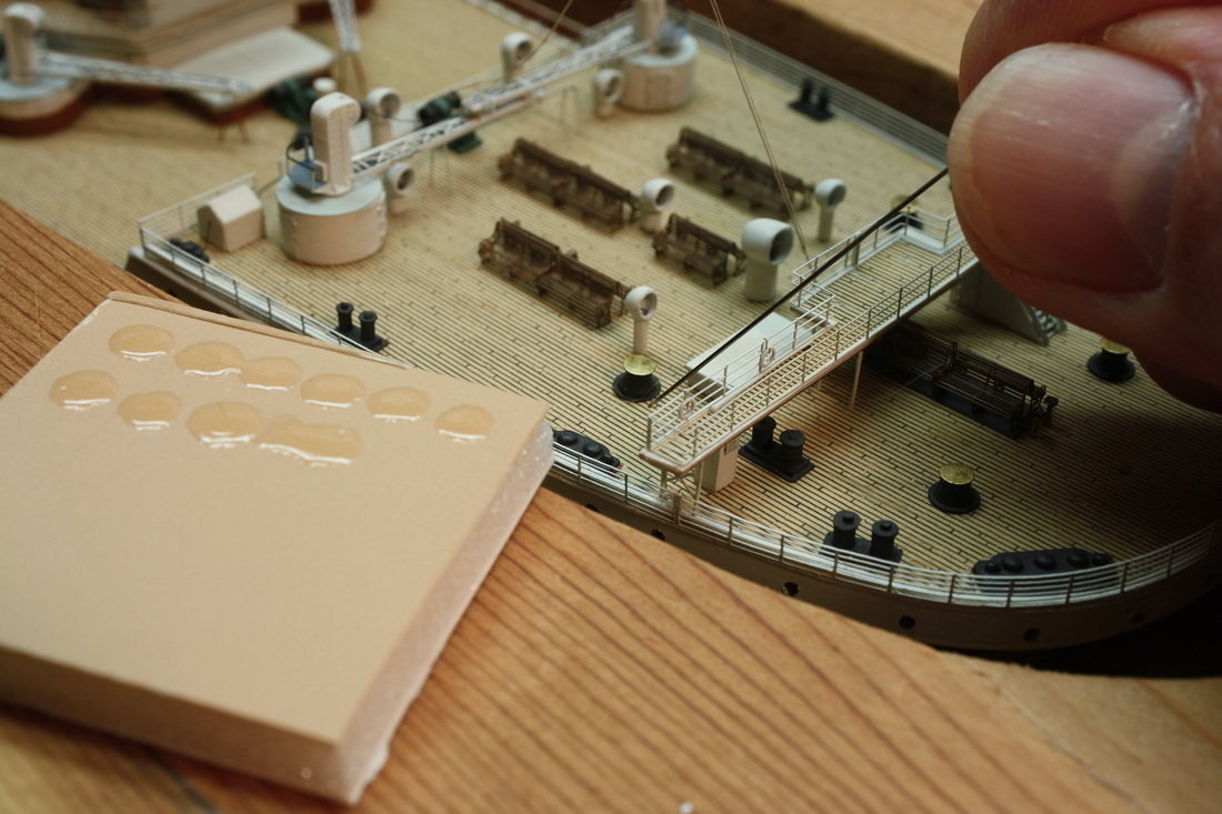
Last: A very fine piece of stainless-steel wire, one end bent into a loop for holding between two fingers, was used as an applicator for applying miniscule amounts of cement to the desired spot. Small glue blocks were cut from foamcore; these could be conveniently set right by the area being worked on after depositing a droplet of glue for pickup with the wire applicator. The wire applicator could be used to lightly wick cement onto an area prior to bonding (below left) or to wick cement into the area where two pieces were already in contact with each other (below right). In most cases the amount of cement, whether styrene or CA, is small enough that the barely visible amount carried by the tip of the wire is more than enough. This simple tool was probably more useful than any other in building this model, and the fine detail work couldn't have been done without it. I have no idea where it came from; there were two others nearly identical to it in my father's old workbench. They're made from piano wire of .016" diameter. They're rigid and almost impossible to bend, so they don't distort from frequent handling.
|
|
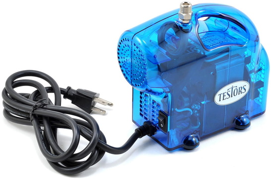
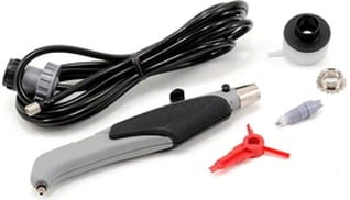
All painting was done with an airbrush. A 'Testor's Blue' (formerly 'Blue Ice') compressor and an Aztek A470 double-action airbrush was used with a grey 9305CX general-purpose nozzle.* This is just a basic setup but it was more than adequate. Few modelers will need an artist's quality airbrush since it's only being used for miniature spraypainting and not artwork.
*This is a nozzle for enamel paints. A different nozzle is required for acrylic (water-based) paints which are increasingly popular.
All airbrushing techniques were self-taught. I had never used an airbrush before working on this model.
*This is a nozzle for enamel paints. A different nozzle is required for acrylic (water-based) paints which are increasingly popular.
All airbrushing techniques were self-taught. I had never used an airbrush before working on this model.
|
|
|
Medium-adhesion blue painter's tape was used for masking the paint breaks on the hull, funnels and deck ladders (stairs) . For the latter, the tape was only pressed onto the parts enough to hold them in place, otherwise the force required to remove them from the tape would have distorted them. Occasionally Titanic modelers have disappointing results with painter's tape peeling up the paint it's applied to, predominantly on the hull. Providing the surface is properly cleaned and the paint properly applied this shouldn't happen, but it can if the wrong type of tape is used. It's important to note that all painter's tapes are not created equal - there are many different types with varying adhesion. The tape used for this model was marketed for masking household walls and trim and has a rubber-based adhesive. Modelers should see what's available in stores in their area and then check the manufacturer's website for specific product information.
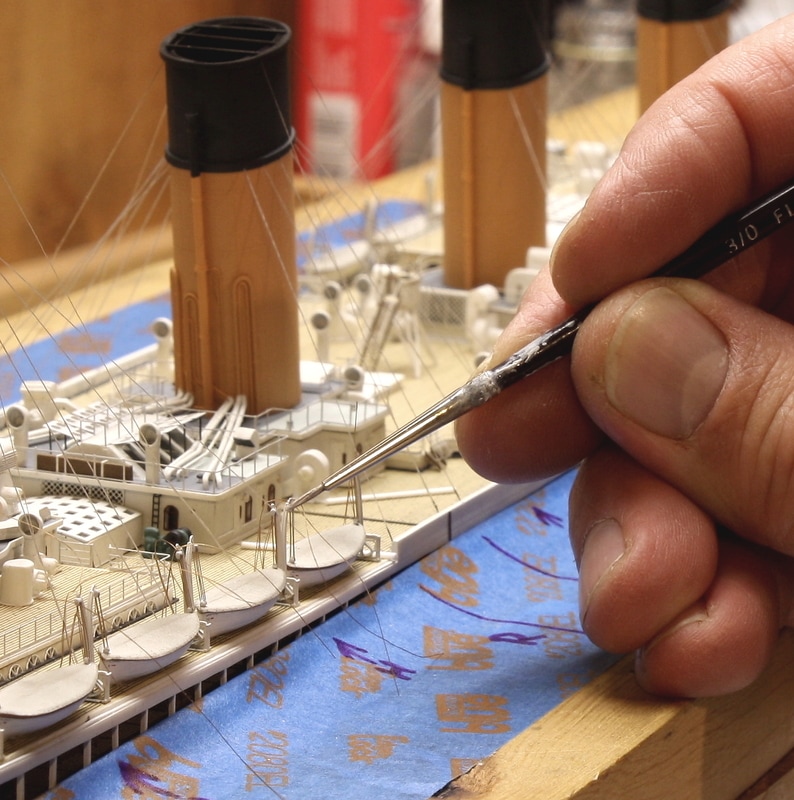
For painting or touching up very small fittings by hand, a 3/0 pure red sable brush was used. A good quality brush costs a little more but will keep a finer, tighter tip better than less expansive alternatives. |
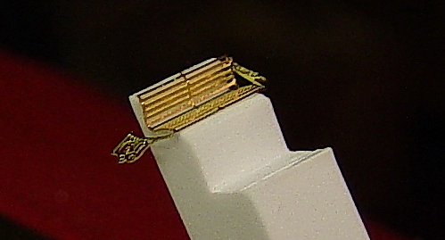
The blue tape in the photo above was not used to mask for painting. Folded back on itself where it touched the ship, it covered the narrow gap to prevent small parts from dropping down inside the graving dock.
|
There are several Titanic model kits available, but the Minicraft is considered the most historically accurate one. It's also the one most supported by photoetched brass for taking it beyond an out-of-the-box build.
If purchasing a kit from a source other than Minicraft, it's strongly recommended that you compare the artwork on the box to the one shown on the Minicraft website at right. With previous versions you risk getting a kit with older parts that are not properly cast or less detailed.. (Click the logo at right for link.) |

|